I often see good parts fail before machining even starts. The problem is not the design. The problem is the file format sent for quote.
The CAD format you send affects machining accuracy, surface quality, engineering time, and even final price. Mesh files like STL lose geometry data. Solid formats like STEP keep precision and reduce manufacturing risk.
I have worked with hundreds of engineers. Many designs are excellent. Some projects still run into delays, extra cost, or quality issues. The root cause is often the wrong file type. I want to explain this from a real machining point of view, based on what I see every day on the shop floor and during quoting.
CAD File Types in Manufacturing: Mesh vs Solid Models?
Many engineers think all 3D files are equal. They are not. The internal data structure changes how we manufacture the part.
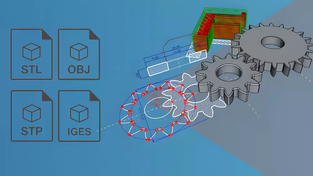
Mesh files like STL and OBJ describe only the outer skin using triangles. STEP and IGES store true geometry with math surfaces and solid bodies, which machining software can read accurately.
Mesh Models (STL / OBJ)
Mesh files break the surface into thousands of small triangles. This works well for graphics and for processes like 3D printing. It does not work well for precision machining. A circle is no longer a true circle. It becomes a many-sided shape. CAM software1 must guess the real geometry. That guess can cause errors in toolpaths and final dimensions.
Solid Models (STEP / IGES)
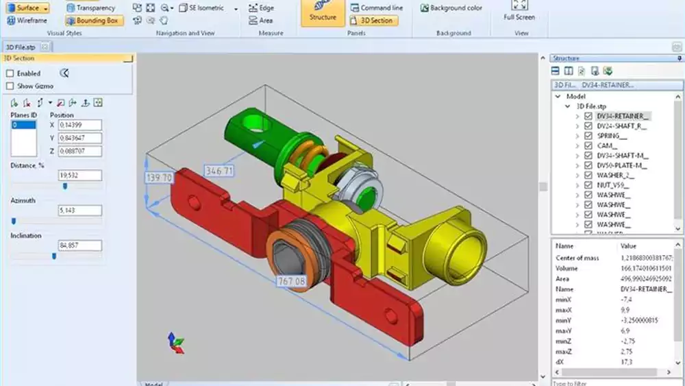
Solid formats2 store cylinders as cylinders and planes as true planes. Fillets have exact radii. Holes have defined axes. CAM systems use this data to build stable toolpaths. I can measure features directly inside the software. I do not need to rebuild the model before programming.
When I receive a STEP file, I trust the geometry. When I receive STL for CNC, I know extra work is coming. That extra work often shows up later in price and lead time.
How File Format Choice Affects Machining Quality?
I have seen surface finish issues and fit problems caused by mesh data. The design was correct. The file was not.
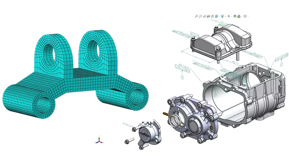
Using STL or OBJ for CNC can lead to faceted curves, unstable toolpaths, and lost feature data. STEP and IGES keep true curves and surfaces, which leads to better accuracy and smoother finishes.
If you want to understand how machining strategy and geometry affect final finish, I explain more in my detailed guide to CNC machining processes. File format plays a big role in how well those processes perform.
Common Problems with Mesh Files in CNC
| Geometry Type | What Happens in STL | Machining Result |
|---|---|---|
| Cylinders | Converted to polygons | Poor bearing or shaft fit |
| Fillets | Broken into flat faces | Visible tool marks |
| Small features | Sometimes missing | Functional risk |
| Threads & holes | Not recognized as features | Manual programming needed |
Mesh models also make 5-axis machining harder. Smooth surfaces become tiny flat patches. The machine slows down because it tries to follow thousands of small segments. Surface finish gets worse. Tool wear increases. If the part has sealing surfaces or sliding fits, this can become a serious functional issue.
Why Solid Files Improve Results
STEP and IGES let CAM software detect features like pockets and holes. Toolpaths follow real curves, not triangle edges. This gives stable cutting and predictable tolerance control. It also helps us achieve consistent surface roughness because the tool moves in smooth paths instead of tiny steps.
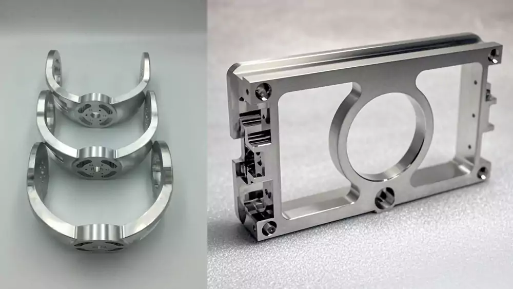
When I machine aerospace or medical parts, I always ask for STEP. It reduces risk. It also reduces the chance that we need to question the design intent.
How CAD Formats Influence Quotation Accuracy and Lead Time?
File format affects price more than many buyers realize. I see this every week when preparing quotes for new parts.
If a supplier must repair or rebuild your model, engineering time increases, risks grow, and quotes become higher and slower. Clean STEP files allow faster, more accurate pricing.
Where Extra Cost Comes From
| File Issue | Supplier Impact | Customer Result |
|---|---|---|
| STL only | Model must be recreated | Higher quote |
| Open surfaces | Geometry repair needed | Longer lead time |
| Missing features | Back-and-forth emails | Delayed approval |
| Low mesh resolution | Shape unclear | Conservative pricing |
When geometry is unclear, I must add safety margins. I may choose slower machining strategies. I may allow extra stock for finishing. All of this protects me from risk. It also increases your cost.
Real Case from My Shop
I once quoted two versions of the same aluminum housing for an automation customer.
| Parameter | STL Version | STEP Version |
|---|---|---|
| Material | 6061-T6 | 6061-T6 |
| Size | 180 × 95 × 60 mm | Same |
| Tolerance | ±0.02 mm | ±0.02 mm |
| Engineering prep time | 3.5 hours | 45 minutes |
| CAM programming time | 2.2 hours | 1.1 hours |
| Quoted price | $428 | $356 |
| Lead time | 12 days | 9 days |
The STL file had rough curves and broken edges. My engineer had to remodel critical faces and bores. That added time and cost. The STEP file3 was clean. We trusted it and moved fast from programming to machining.
This is why I say file format affects quotation accuracy. Bad data forces suppliers to add hidden engineering time and risk buffers.
Best Practices: Choosing and Preparing CAD Files for CNC and 3D Printing?
I want customers to get the best price and smooth production. A few simple steps make a big difference.
Use STEP for CNC machining and STL for 3D printing. Always include tolerances, materials, and critical function notes. Good data reduces risk, cost, and delays.
Recommended Formats by Process
| Process | Best Format | Why |
|---|---|---|
| Precision CNC | STEP | Full solid geometry |
| Complex surfacing | IGES | Good surface transfer |
| 3D printing | STL | Machine-ready mesh |
| Visual models | OBJ | Rendering only |
When to Convert STEP to STL
Only convert when preparing for 3D printing. Use high mesh resolution. Low resolution creates flat spots and size errors. I suggest checking deviation settings under 0.01 mm for functional prototypes. For visual models, resolution can be lower. For parts that must assemble, keep it fine.
File Submission Checklist
- Send STEP for machined parts
- Add 2D drawings for tight tolerances
- Mark critical surfaces and fits
- State material and finish
- Mention assembly function
When I receive complete and correct data, I quote faster and more accurately. Production also runs smoother. Good files help both sides win.
Conclusion
File format is not just a technical detail. It directly affects quality, cost, and delivery. Sending the right CAD file helps your supplier succeed and protects your project.

-
Explore how CAM software interprets different model types to understand its impact on machining accuracy and toolpath generation. ↩
-
Learn why solid formats provide more reliable geometry for CNC programming, reducing errors and saving time in manufacturing. ↩
-
Learn why STEP files provide cleaner data, reduce engineering prep time, and result in more accurate quotes and faster production. ↩
