Final Tolerance Knowledge Guide: What you need to know about tolerances in manufacturing!
- December 10, 2024
- Tony
In manufacturing and design, tolerance is crucial for ensuring part quality and accurate assembly. Whether for mechanical components, electronics, or precision instruments, controlling tolerances is key to achieving high-quality products.
1. What is tolerance?
Tolerance defines the allowable variation in a part’s dimensions, setting the acceptable difference between the intended size and the actual measurement.
In manufacturing, parts may deviate slightly due to factors like material properties and process limitations. Tolerances establishes the permissible range for these variations.
Example:
If a hole is designed to be 10mm, a tolerance might allow the actual size to be between 9.98mm and 10.02mm. This range ensures the part functions properly and meets the required specifications.
2. When do we need tolerance?
Assembly requirements:
Precise fits between different parts are required to ensure smooth assembly. For example, shafts and holes require a very tight fit to ensure the stability of the assembly.
Functional requirements:

The size and shape of some parts must be precise to ensure that they work properly. For example, precision parts such as gears and bearings require strict tolerance control.
Production process:
Each manufacturing process (e.g. milling, turning, injection molding, etc.) has its own applicable tolerance range, beyond which may lead to processing failure or substandard quality.
3. How is the tolerance expressed?
Tolerances are usually expressed through the following three aspects:
- Dimensional Tolerance:
It is the permissible range of deviation in the dimensions of a part, e.g., the diameter of a hole, the length of a part, etc. - Shape Tolerance:
Shape tolerances are the allowable deviations in the surface shape of a part, e.g. flatness, roundness, etc. - Positional Tolerance:
Refers to the positional deviation of a geometric feature of a part with respect to other features, e.g., locality, coaxiality, etc.
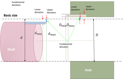
4. Important terms for tolerancing
- Basic Size: It is the ideal size specified at the time of design and is used to calibrate other sizes.
- Actual Size: The actual size of the part obtained by measurement.
- Limit Size: Indicates the maximum and minimum allowable values for dimensional variation.
- Dimensional Deviation: The difference between the actual size and the basic size.
- Dimensional Variation: The dimensional tolerance, which indicates the permissible range of dimensional fluctuation.
- Zero line: A reference line indicating the basic size and used to determine the range of deviation.
- Tolerance band: The area defined by the upper and lower deviations, indicating the permissible range of dimensional variation.
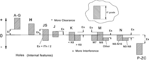
5. Types of fits
Fitting is an important application area of tolerance, especially in the matching of holes to shafts. Fits can be categorized into the following types:
1. Clearance fits:
The size of the hole is larger than the size of the shaft, usually used where spatial freedom is required.
2. Excess fit:
The size of the shaft is larger than the size of the hole, usually used where a tight fit is required.
3. Transition fit:
Hole and shaft dimensions are close, but not exactly matched, allowing a slight clearance or interference.
Application Example (Hole and Shaft Fit)
Suppose a hole and shaft fit is designed, where the basic size of the hole is 10 mm. to ensure a proper fit between the hole and the shaft, different tolerances are set for the hole and shaft:
If the size of the hole is 10mm and the maximum limit size is 10.02mm and the minimum limit size is 9.98mm, then we have a dimensional tolerance.
The shaft is designed for a size of 9.95 mm with an allowable limit size of 9.93 mm to 9.97 mm. By setting these tolerances, it is ensured that the shaft can enter the hole without any problem and at the same time not be too loose or too tight.
6. Terms used in metric tolerance
- Basic Size: The ideal size specified at the time of design.
- Actual Dimensions: The actual dimensions of the part obtained by measurement.
- Limit dimensions: Maximum and minimum values of the permissible dimensional range.
- Dimensional Deviation: The difference between the actual size and the basic size.
- Dimensional Tolerance: The difference between the maximum limit size and the minimum limit size.
- Zero Line/Tolerance Zone: The reference line and zone used to indicate the tolerance range.
- Standard Tolerance and Standard Tolerance Grade: The grade of dimensional accuracy specified in national standards.
- Basic deviation: Generally refers to the deviation close to the zero line
7. International standards for tolerance grades
In mechanical engineering, tolerances define the permissible range of dimensional deviations for a part. To standardize these criteria, the International Organization for Standardization (ISO) has established 20 standard tolerance grades to indicate the accuracy of machined dimensions.
These grades are expressed as “IT” followed by a number, e.g., IT01, IT0, IT1 to IT18, with lower numbers indicating higher precision and narrower tolerances. Specifically:
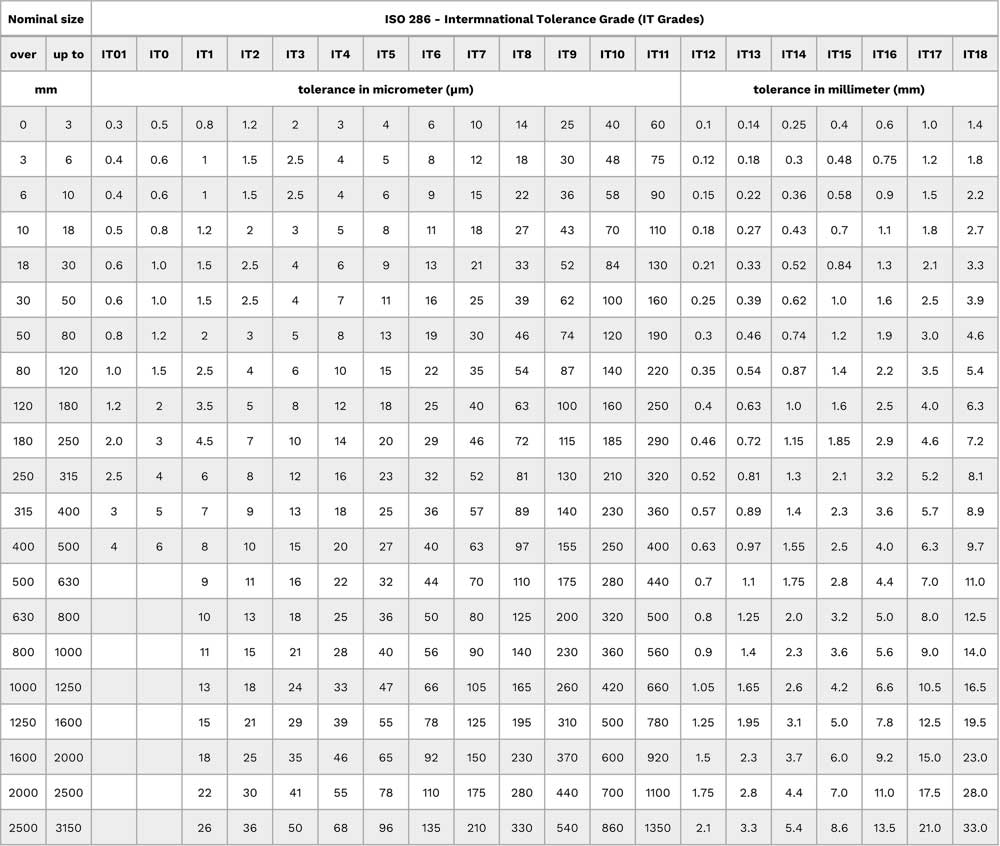
- IT01: Highest precision, used in aerospace and other high-precision fields.
- IT0: Ultra-high precision, for applications with extreme dimensional accuracy requirements.
- IT1 to IT3: High precision, commonly used in precision instruments and key components.
- IT4 to IT6: Medium precision, suitable for general mechanical parts.
- IT7 to IT11: Coarse precision, for parts not requiring high accuracy.
- IT12 to IT18: Ultra-coarse precision, mainly for rough machining processes like casting and forging.
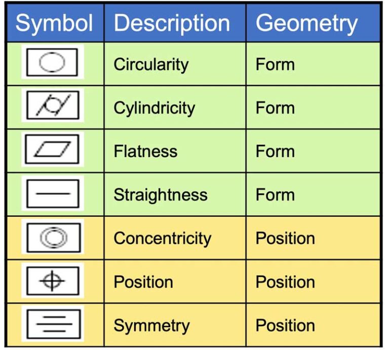
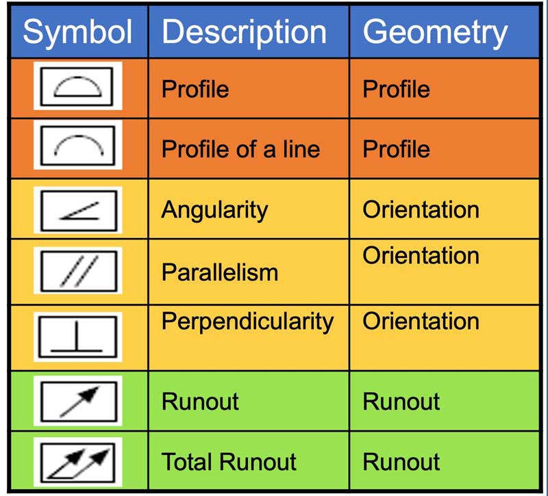
8. Basic symbols for common tolerance
9. Summary
Tolerances are essential in manufacturing to ensure parts fit properly and meet functional needs. Understanding the basics of tolerances will help you make better design and production decisions.
For more guidance or assistance with tolerancing, feel free to consult our manufacturing experts for a precise solution.
