Last updated on May 12, 2026, by Lucy
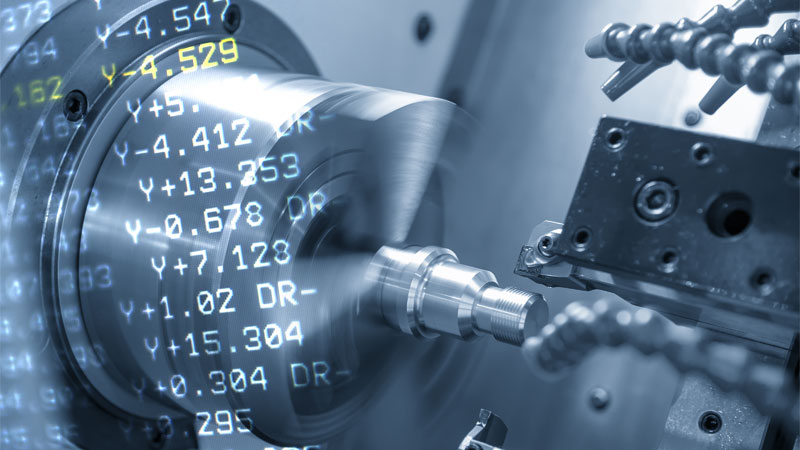
A CNC machine can destroy a tool, scrap material, or stop production from one small programming mistake. Many engineers trust software but never understand the code behind the cut.
G-code is the programming language used in CNC machining to control machine movement, cutting paths, spindle speed, feed rate, tool changes, and machining operations. It converts digital part designs into machine-readable instructions so CNC equipment can manufacture accurate and repeatable parts.
Behind every finished CNC part is a sequence of instructions. CAD creates the design. CAM generates the toolpath. G-code tells the machine what to do next. Once you understand this workflow and how modern CNC machining services execute programmed instructions, CNC manufacturing becomes much easier to understand.
What Is G-Code in CNC Machining?
Many people think a CNC machine can read a 3D model and machine a part automatically. That is not how it works. Machines need exact instructions.
G-code is a standardized CNC programming language that tells a machine where to move, how fast to move, what tool to use, and what machining action to perform.
G-code may look simple at first. It is mostly letters and numbers. But each command controls a specific machining action. That is why even modern automated shops still rely on clean code.
What Does G-Code Stand For?
G-code stands for Geometric Code.
The letter G represents geometry-based machine commands. These commands tell a CNC machine how to move through space.
Common movement instructions include:
- Linear motion
- Circular interpolation
- Rapid travel
- Coordinate positioning
- Tool compensation
Example:
| Code | Meaning |
|---|---|
| G00 | Rapid positioning |
| G01 | Linear cutting move |
| G02 | Clockwise arc |
| G03 | Counterclockwise arc |
| G90 | Absolute positioning |
These commands control motion along X, Y, and Z axes.
Why G-Code Is Essential in CNC Manufacturing
A CNC machine cannot interpret a drawing by itself.
The manufacturing workflow usually looks like this:
- CAD creates the geometry
- CAM creates toolpaths
- G-code sends executable instructions to the machine
Without G-code:
- No cutting movement
- No drilling logic
- No spindle control
- No repeatable production
This matters in industries where part accuracy matters most:
- Aerospace
- Automotive
- Medical devices
- Robotics
- Consumer electronics
A single wrong line of code can ruin a high-value part.
Who Uses G-Code?
G-code is not only for machinists.
People who benefit from understanding G-code include:
- CNC programmers
- Operators
- Manufacturing engineers
- Mechanical engineers
- Purchasing managers sourcing custom parts
A buyer does not need to write code. But understanding basic G-code helps identify capable suppliers and reduce production risk.
How Does G-Code Work in a CNC Machine?
Many beginners understand what G-code is but still do not understand how it controls a machine.
G-code works by sending line-by-line instructions to a CNC machine, defining axis movement, spindle behavior, cutting depth, tool changes, and machining sequence.
A CNC controller reads the code one line at a time. Each line is executed in sequence.1
This means machining is not random. Every motion is intentional.
Before looking at common commands, it helps to see how a program is structured.
Basic Structure of a G-Code Program2
A simple CNC program:
%
O1001
G21
G90
G00 X0 Y0
M03 S3000
G01 Z-2 F100
G01 X50 Y50 F300
M05
M30
%
Program breakdown:
| Line | Function |
|---|---|
| G21 | Metric units |
| G90 | Absolute coordinates |
| G00 | Rapid move |
| M03 | Spindle on |
| S3000 | 3000 RPM |
| G01 | Controlled cutting |
| F100 | Feed rate |
How G-Code Controls Machine Movement
A CNC machine follows coordinates.
Example:
G01 X100 Y50 Z-5 F200This command means:
- Move to X100
- Move to Y50
- Cut to Z-5 mm
- Feed at 200 mm/min
This one line defines both motion and machining conditions.
Example of a Simple G-Code Program
Basic drilling example:
G90
G00 X20 Y20
M03 S2500
G81 X20 Y20 Z-10 R2 F120
M05
This program drills one hole at a specific coordinate.
Machines repeat this logic thousands of times in production. For readers who want a broader reference of commands beyond beginner examples, this detailed G-code list guide covers commonly used programming instructions in more depth.
Common G-Code Commands and CNC Programming Basics
New users often think they need to memorize hundreds of commands. Most CNC programs only rely on a smaller group of common instructions.
Most beginner CNC programming uses a core set of G-codes for movement, positioning, interpolation, drilling, and coordinate control.
Once you understand the common commands, reading CNC programs becomes much easier.
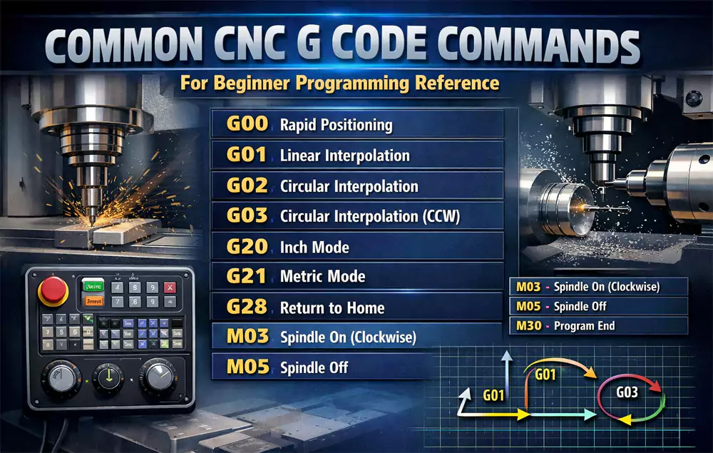
Most Common G-Code Commands for Beginners
| G-Code | Description |
|---|---|
| G00 | Rapid positioning |
| G01 | Linear interpolation |
| G02 | Clockwise arc |
| G03 | Counterclockwise arc |
| G17 | XY plane selection |
| G20 | Inch mode |
| G21 | Metric mode |
| G28 | Return home |
| G54 | Work offset |
These commands appear in most CNC milling programs.
Difference Between G-Code and M-Code
Many beginners confuse G-code and M-code.
G-code controls machine movement and geometry, while M-code controls machine functions such as spindle rotation, coolant, and tool changes.
| Type | Purpose |
|---|---|
| G-code | Motion and positioning |
| M-code | Machine functions |
Common M-codes:
| M-Code | Meaning |
|---|---|
| M03 | Spindle on clockwise |
| M05 | Spindle stop |
| M06 | Tool change |
| M08 | Coolant on |
| M30 | Program end |
G-code tells the machine where to go.
M-code tells the machine what to activate.
G-Code Programming Tips
My basic programming rules:
- Simulate before machining
- Verify work offsets
- Confirm units
- Check spindle speed
- Review tool length offsets
Small mistakes often create expensive problems.
Common G-Code Errors, Software Tools, and Best Practices
Most CNC issues are not caused by broken machines. They are caused by preventable programming mistakes.
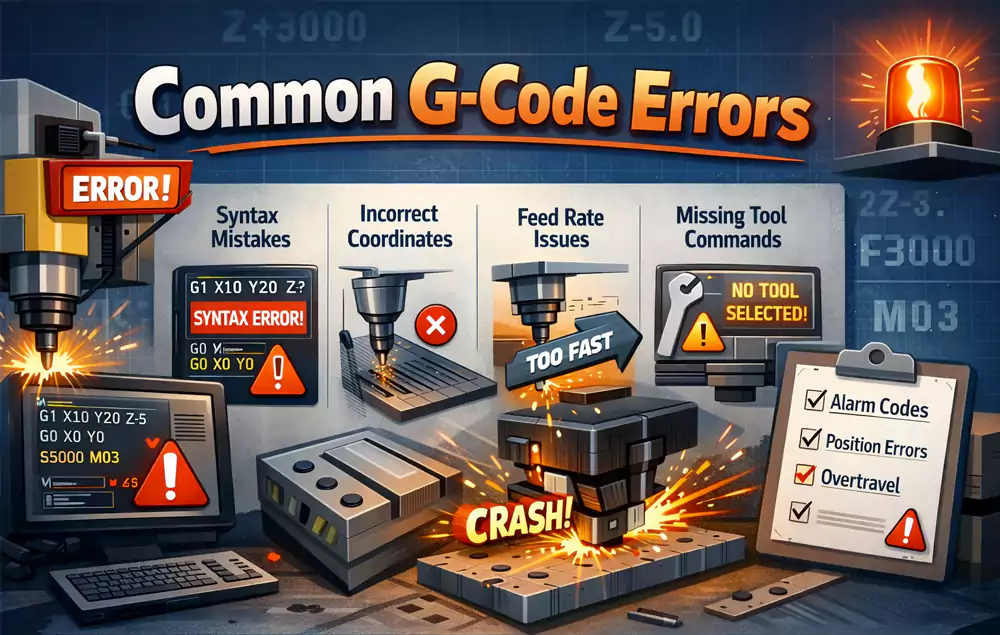
Common G-code errors include incorrect coordinates, wrong units, missing offsets, unsafe spindle speeds, and feed rate mistakes that lead to scrap or tool crashes.
Understanding common errors helps both machinists and engineers avoid unnecessary cost.
Common G-Code Errors and Solutions
| Error | Cause | Fix |
|---|---|---|
| Tool crash | Wrong Z value | Simulate first |
| Oversized feature | Wrong compensation | Check offsets |
| Mirrored geometry | Wrong sign value | Verify origin |
| Broken tool | Feed too high | Adjust parameters |
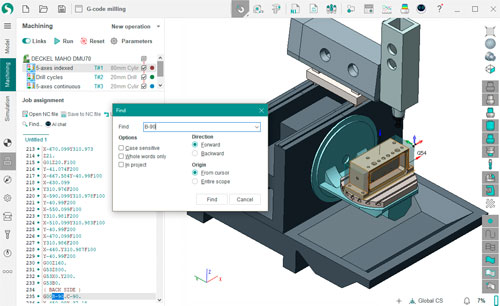
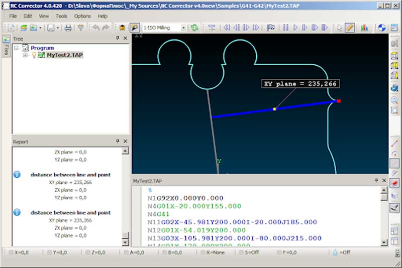
Best Free G-Code Editors and Simulators
Useful beginner tools:
- NC Viewer
- CAMotics
- Fusion 360 Personal
- Candle
- Universal Gcode Sender
These tools help visualize code before machining.
Case Study: Aluminum Bracket Programming Optimization
I once reviewed a CNC program for an automation customer machining aluminum brackets.
Machining parameters before optimization:
| Parameter | Value |
|---|---|
| Material | 6061-T6 Aluminum |
| Machine | 3-axis VMC |
| Tool | 8 mm carbide end mill |
| RPM | 12000 |
| Feed | 1800 mm/min |
| Depth per pass | 3 mm |
Problem:
- Tool chatter
- Poor wall finish
- High scrap rate
Results after code optimization:
| Parameter | Before | After |
|---|---|---|
| Surface roughness | Ra 3.8 μm | Ra 1.4 μm |
| Cycle time | 14 min | 12 min |
| Scrap rate | 8% | 1.2% |
Changes made:
- Reduced radial engagement to 25%
- Feed adjusted to 1450 mm/min
- Added finishing pass with G41 compensation
This was not a machine limitation. It was a programming issue.
Why Understanding G-Code Matters for Custom CNC Parts
Even if you never write CNC code manually, understanding G-code helps you:
- Review manufacturability
- Communicate with suppliers
- Reduce machining risk
- Improve tolerance consistency
- Troubleshoot part issues faster
CAM software gives speed.
Reading G-code gives control.
Strong manufacturing teams usually understand both, especially when evaluating production workflows used by experienced CNC machining services.
Conclusion
G-code is the foundation of CNC machining. Understanding how it works helps engineers improve part quality, reduce machining risk, and make smarter manufacturing decisions.

-
"G-Code Basics: Program Format and Structure - CNC Cookbook", https://www.cnccookbook.com/g-code-basics-program-format-structure-blocks/. NIST’s RS274/NGC interpreter documentation describes CNC programs as sequences of blocks that are interpreted and executed according to the programmed order, supporting the article’s description of line-by-line logical execution. Evidence role: mechanism; source type: government. Supports: A CNC controller reads G-code program lines and executes them sequentially.. Scope note: Modern controllers may use buffering or look-ahead internally, so the source supports the logical programming model rather than every controller’s physical execution timing. ↩
-
"Numerical Control Programming - Chapter 3", http://faculty.etsu.edu/hemphill/entc3710/nc-prog/nc-prog-03.htm. A standard CNC programming reference can substantiate that G-code programs are organized as sequential blocks containing preparatory functions such as unit selection and coordinate mode, motion commands, spindle/feed settings, and program-end commands. Evidence role: definition; source type: education. Supports: A G-code program has a basic structure made up of sequential lines or blocks that define units, coordinate mode, motion commands, spindle/feed settings, and program termination.. Scope note: Exact syntax and required header/footer elements can vary by CNC controller and machine-tool dialect. ↩
