Designing parts with internal grooves or hidden features? Undercutting is often the key—but standard tools may not reach these areas, causing manufacturability challenges, delays, and higher costs.
Undercutting in machining is the process of creating a groove or recess that is inaccessible to a standard straight cutting tool. It requires specialized tools and toolpaths to machine these hidden features.

In my 20 years as a CNC machinist, I've learned that some of the most challenging—and clever—features on a part are the ones you can't easily see. Undercuts fall squarely into this category. For an engineer like David, who designs complex components for automation, understanding undercuts is essential. It's a feature that demands both smart design and skilled execution. An undercut can be an elegant solution for creating seals, locks, or tool clearances, but it requires careful planning from both the designer and the machinist. This isn't just about having the right tool; it’s about knowing how to use it, and when. I've seen firsthand that poor planning here leads to costly rework, which is why a deep understanding of the process is so important for everyone involved.
What Is the Purpose of Undercutting?
Why would a designer intentionally create a feature that is difficult to machine? What functional purpose does an undercut serve in a mechanical part?
The purpose of Undercutting is to create internal features that enable hidden interlocking of components without external fasteners, provide necessary clearances for threading or grinding tools, and incorporate special functions such as O-ring grooves for sealing in confined spaces.
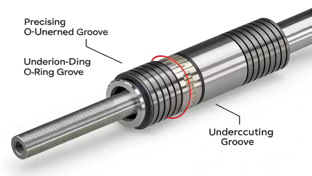
Critical Functions Explained
Undercuts perform jobs visible geometry can't handle. Let’s break down their key roles:
| Function | Real-World Example | Impact |
|---|---|---|
| Mechanical Locking | Plastic housing clips | Eliminates screws/threads |
| Sealing Surfaces | Hydraulic valve grooves | Secures O-rings under pressure |
| Component Clearance | Bearing seat reliefs | Prevents interference during assembly |
| Weight Reduction | Aerospace brackets | Removes material where strength isn't critical |
Diving Deeper into the Function of Undercuts
An undercut is rarely added for aesthetic reasons; it almost always serves a critical functional purpose. While it adds complexity to the CNC machining process, it can simplify the overall product design and assembly. For an engineer, an undercut is a powerful design tool to solve specific mechanical challenges.
Here are the primary purposes of undercutting:
-
Creating Grooves for Sealing Elements:
- This is one of the most common uses. An internal groove is machined to house an O-ring, seal, or retaining clip1. This allows for a secure, sealed connection between two mating parts. Creating this internal groove as an undercut is often the only way to place a seal exactly where it needs to be.
-
Providing Tool Relief or Clearance:
- When a part needs to be threaded or ground, an undercut is often created at the end of the feature. This "thread relief2" or "grinding relief" is a small groove that is slightly deeper than the threads or ground surface. It gives the cutting or grinding tool a place to "run out" or exit the cut cleanly without crashing into a shoulder. This ensures a full, functional thread right to the end.
-
Creating Interlocking or Latching Features:
- Undercuts are used to create features that allow parts to snap or lock together. Think of the locking tabs on many plastic components. In machined parts, a similar internal groove can be used as a locking feature for a mating part.
-
Weight Reduction:
- In some high-performance applications, internal undercuts can be designed to remove material from non-critical areas to reduce the overall weight of the part without compromising its structural integrity.
In all these cases, the undercut provides a necessary geometric feature that cannot be achieved with a simple, straight-line machining approach.
How Does Undercutting Work?
How does a machine create a feature that it can't reach directly from the top? What is the actual mechanical process of undercutting in a CNC machine?
Undercutting works by using a specially shaped cutting tool that is fed sideways into the workpiece after being positioned inside a larger cavity or bore, cutting a feature from the inside out.
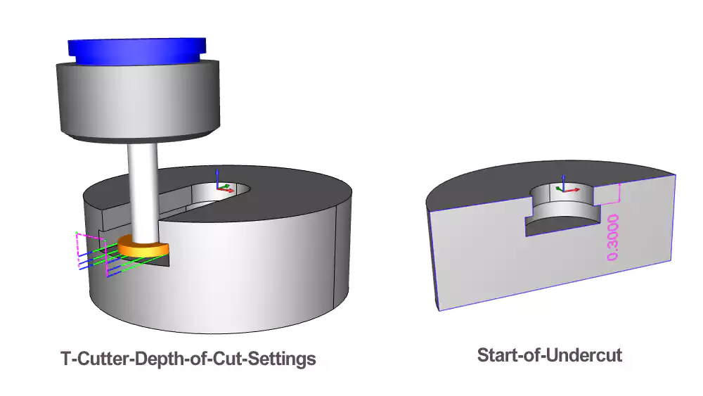
Process Breakdown
Successful undercutting requires precise sequencing:
-
Tool Selection
T-slot cutters3, lollipop mills, or custom ground tools match the undercut profile -
Access Strategy
Machinists identify entry points through existing holes or cavities -
Path Programming
CAM software plots gradual radial engagement to avoid tool breakage -
Finishing Passes
Light final cuts ensure surface finish in hidden areas
Diving Deeper into the Undercutting Process
The process of undercutting in CNC machining is a clever sequence of movements that allows a tool to cut where it otherwise couldn't reach. It feels counter-intuitive, which is why it requires careful planning. For engineers, visualizing this process can help in designing features that are manufacturable.
Here’s a breakdown of how a typical undercut operation works on a CNC mill or lathe:
-
Entry and Positioning:
- First, a primary cavity or bore must already exist. You cannot create an undercut on a solid surface. A standard end mill or drill creates a pocket or hole that is large enough for the non-cutting part of the undercutting tool (the shank) to enter.
- The specialized undercutting tool is then lowered into this pre-machined cavity. The machine positions the tool so that its cutting edges are aligned with the location of the desired internal feature.
-
The Sideways Cut:
- This is the key step. Once in position, the tool is fed sideways (along the X or Y axis in a mill, or the X axis in a lathe) into the wall of the part. The specially shaped cutting edges on the side of the tool engage with the material and begin to cut the groove or recess.
- This cut is often performed with a circular or arcing toolpath, moving the tool around the inside of the part to create a continuous groove.
-
Retraction:
- After the feature is fully machined to the specified depth and diameter, the tool is carefully retracted back to the center of the cavity. It is then pulled straight out of the part.
The entire process relies on having enough clearance within the main cavity for the tool's shank and being able to feed the tool sideways to make the cut. Because the cutting forces are applied sideways and the tools are often less rigid, speeds and feeds are typically more conservative than in standard machining. It is a precise and deliberate operation from start to finish.
What are typical undercuts in CNC machining?
What do these hidden features actually look like? What are some of the standard or common types of undercuts that are designed into machined parts?
Typical undercuts include internal grooves for O-rings and retaining rings (snap rings), J-grooves, D-grooves for specific sealing profiles, and thread reliefs at the end of a threaded section.
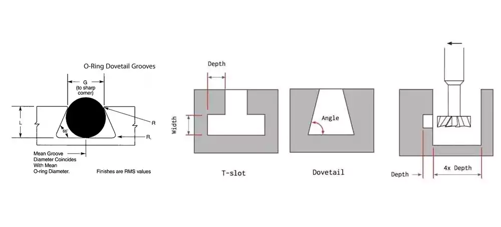
Diving Deeper into Common Undercut Geometries
While an undercut can be almost any shape that is "hidden" from a direct toolpath, several common geometries are frequently used in engineering design. For David, designing with these standard types in mind can often lead to more cost-effective manufacturing, as machine shops are familiar with them.
Here are some of the most typical undercuts found in CNC machined parts:
-
O-Ring Grooves:
- This is arguably the most common type of undercut. It is a simple rectangular or square-profiled groove machined on the inside diameter of a bore. Its purpose is to hold a rubber O-ring to create a reliable seal against a shaft or piston.
-
Retaining Ring Grooves (Snap Ring or Circlip Grooves):
- Similar to an O-ring groove, this is a narrow, precise groove machined inside a bore or on the outside of a shaft. It is designed to hold a retaining ring, which is a type of fastener used to prevent a component from moving along the axis of the shaft.
-
Thread Reliefs (Undercuts):
- When cutting threads up to a shoulder, it's difficult to get a full, perfect thread at the very end. A thread relief is a small undercut machined at the base of the shoulder, slightly deeper than the thread's minor diameter. This allows the threading tool to complete its cut cleanly, ensuring a fully functional thread along the entire required length.
-
D-Grooves and J-Grooves:
- These are undercuts with specific profiles, shaped like the letters "D" or "J". They are often used for specialized seals, electrical connectors, or unique locking mechanisms where a simple rectangular groove is not suitable.
-
T-Slots:
- While often machined from the outside, an internal T-slot is a type of undercut. It's a slot with a wider channel at the bottom, used for mounting special T-nuts or for creating sliding-and-locking features.
Understanding these common types helps designers and machinists communicate clearly about the specific feature required for the part.
What Specialized Tools Are Used for Undercutting?
You can't use a standard end mill to create an undercut. What specific types of cutting tools are designed for this purpose, and what do they look like?
Tools for undercutting include T-slot cutters, dovetail cutters, and lollipop cutters (key-seat cutters). These tools have cutting edges on their side and a smaller shank, allowing them to cut sideways.
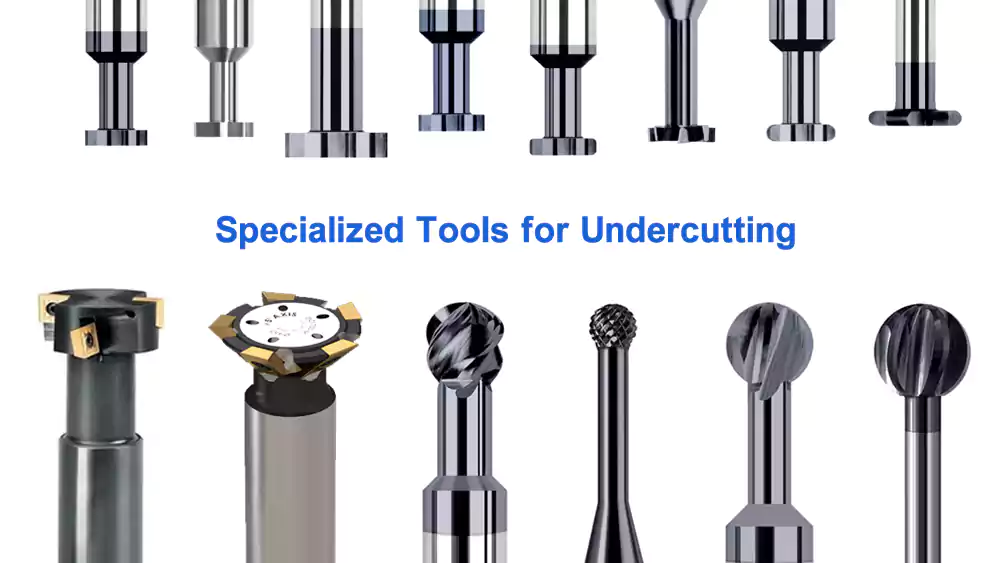
Diving Deeper into Undercutting Tooling
Creating undercuts in CNC machining is impossible without specialized cutting tools. These tools are designed with a unique geometry: their cutting diameter is larger than their shank diameter. This allows the shank to fit into a pre-machined hole or slot while the larger cutting head reaches out to machine the hidden feature.
Here are the main types of tools used for undercutting:
-
T-Slot Cutters:
- Description: These tools look like a small disc-shaped cutter on the end of a long shank. They have cutting teeth on both the face and the periphery of the disc.
- Primary Use: As the name suggests, they are designed for machining T-slots. However, they are also commonly used to create simple square or rectangular undercuts and O-ring grooves inside a bore.
-
Dovetail Cutters:
- Description: Similar to a T-slot cutter, but the cutting head is angled, typically at 45 or 60 degrees.
- Primary Use: Designed for machining dovetail slides, a common feature in machine tool construction. They are also used to create angled undercuts or chamfers on the backside of a hole.
-
Lollipop Cutters (or Key-Seat Cutters):
- Description: These are spherical or ball-shaped cutters on the end of a shank. They have cutting edges that extend more than 180 degrees around the ball, allowing them to cut on the bottom, side, and top surfaces.
- Primary Use: They are extremely versatile for 3D contouring and are excellent for creating complex undercut shapes, deburring the backside of a hole, or machining full radius grooves (D-grooves).
-
Grooving and Boring Bars (for Lathes):
- Description: On a CNC lathe, undercuts are created with specially shaped boring bars. These tools have a small, custom-ground insert or tip that protrudes sideways from the end of the bar.
- Primary Use: These are used exclusively for creating internal grooves and profiles on turned parts.
Choosing the right undercutting tool is a critical decision for the machinist and depends entirely on the specific geometry of the part the engineer is designing.
What are the Main Design Considerations in Undercut Machining?
To ensure an undercut is manufacturable and cost-effective, what should an engineer consider? What are the key design for manufacturability (DFM) rules for undercuts?
Key design considerations include providing sufficient clearance for the tool's shank, using standard corner radii where possible, keeping the undercut depth reasonable, and ensuring the feature is reachable by the tool.
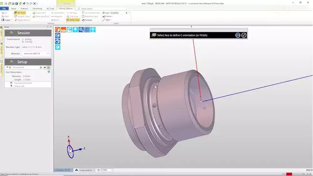
Diving Deeper into Design for Manufacturability (DFM)4
As I always tell my clients, the most successful projects happen when the design engineer and the machinist work together. For a feature as complex as an undercut, following good Design for Manufacturability (DFM) principles is essential. For David, keeping these points in mind during the design phase will save time and money down the line.
Here are the main design considerations:
-
Tool Clearance and Access:
- The most critical rule. The main bore or entry hole must be large enough for the non-cutting shank of the undercutting tool to pass through with adequate clearance. If the entry hole is too small, the operation is impossible.
-
Corner Radii:
- Sharp internal corners are always difficult and expensive to machine. Undercutting tools naturally create a radius in the corner where the groove meets the back wall. Designers should specify the largest acceptable corner radius, as this allows for the use of a stronger, more standard tool. Trying to achieve a perfectly sharp corner is often impossible and always costly.
-
Depth and Width of the Undercut:
- The deeper an undercut is relative to its width, the more difficult it is to machine. A long, slender cutting tool is less rigid and more prone to vibration (chatter) and deflection, which can lead to poor surface finish and dimensional inaccuracy. Keeping the depth-to-width ratio as low as possible is good practice.
-
Tool Reach:
- The undercut must be located at a depth that the tool can physically reach. Every undercutting tool has a maximum reach, limited by the length of its shank. A feature designed too deep inside a part may not be accessible.
-
Use Standard Groove Sizes:
- If the undercut is for a standard component like an O-ring or retaining ring, design the groove to the standard dimensions recommended by the seal or ring manufacturer. This ensures proper function and allows the machine shop to use standard tooling.
I rejected a client’s magnesium housing design last month because 0.3mm corner radii caused tool fractures. We redesigned with 0.8mm radii and machined successfully. For deep undercuts in stainless steel, consider stepped profiles rather than single-depth features - they reduce tool stress by 60%. Always position undercuts away from weld lines in molded plastics. Critical takeaway: consult your machining partner before finalizing drawings. What looks feasible in CAD often ignores tool physics. We’ve saved clients weeks of rework by adjusting undercut orientations to match standard tool approaches.
How to realize efficient undercutting?
Beyond just having the right tool, what makes an undercutting operation efficient and accurate? What are the key process strategies a machinist uses?
Efficient undercutting is realized through rigid workholding, optimized CAM toolpaths, conservative speeds and feeds to manage cutting forces, and multiple shallow passes instead of one heavy cut.
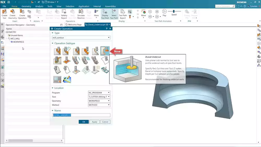
Diving Deeper into Efficient Machining Strategies
From a machinist's perspective, executing an undercut efficiently requires a focus on stability and control. The tools are less rigid, and the cuts are less supported than in standard machining. My team at Allied Metal focuses on these key strategies to ensure a high-quality result.
1. Rigid Setup
- Workholding: The workpiece must be held with absolute rigidity. Any vibration in the setup will be magnified at the tip of the less-rigid undercutting tool, resulting in chatter and a poor surface finish.
- Tool Holding: Using a high-quality, rigid tool holder is essential. The tool should be held with the shortest possible overhang to maximize its stability.
2. Optimized CAM Toolpaths
- Modern CAM software is crucial for efficient undercutting. Instead of just plunging and feeding sideways, the software can generate smooth, arcing entry and exit paths for the tool.
- It also allows for multiple shallow passes. Instead of trying to cut the full depth of the groove at once (which would create very high cutting forces), we program the tool to take several smaller, incremental cuts. This "nibbling" approach reduces the load on the tool, minimizes deflection, and results in a much more accurate feature and better surface finish.
3. Conservative Speeds and Feeds
- While we generally like to run fast in CNC machining, undercutting is a place for caution. Because the tool is less stable, we typically reduce the cutting speed (RPM) and feed rate compared to a standard milling operation.
- This helps to manage the cutting forces, reduce the risk of chatter, and prolong the life of the specialized tool. The goal is accuracy and a good finish, not maximum material removal rate.
4. Effective Coolant and Chip Evacuation
- Getting coolant into an internal groove and getting chips out can be challenging. We use high-pressure coolant directed at the cutting zone to flush chips away and prevent them from being re-cut, which would damage the surface finish.
By combining these strategies, we can perform undercutting operations that are both efficient and meet the tight tolerance requirements of demanding engineers like David.
For a recent aerospace order, we reduced undercut machining time by 35% using high-efficiency toolpaths that maintain constant tool engagement. In aluminum, climb milling produces better surface finishes but conventional milling offers more predictable tool deflection. For critical undercuts, always include a spring pass - one final light cut that removes just 0.01mm to compensate for tool pressure. We implement this on all medical device components. Coolant direction matters tremendously: position nozzles to directly flush chips from deep cavities.
One forgotten tip: machine undercuts early in the process while the workpiece still has maximum rigidity.
What are the applications for undercut parts?
Where are these specialized undercut features actually used? What are some real-world examples of parts and industries that rely on undercutting?
Undercut parts are widely used in the medical, automotive, aerospace, and hydraulics industries for components like fluid connectors, valve bodies, snap-fit enclosures, and threaded fittings.
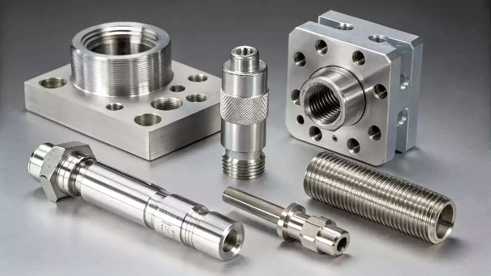
Diving Deeper into Real-World Applications
Undercuts are found in countless mechanical components across many advanced industries. They are often the unseen feature that enables a product to function correctly. For an engineer like David, seeing these applications can spark ideas for solving his own design challenges.
Here are some prominent examples:
-
Hydraulics and Pneumatics:
- Valve Bodies and Manifolds: These components are full of internal passages and chambers. Undercuts are essential for creating the grooves that hold O-rings and seals, preventing fluid or air from leaking between passages.
-
Medical Devices:
- Connectors and Fittings: Luer-lock connectors and other medical fittings often use undercuts to create locking or sealing features. The smooth, cleanable surfaces that can be achieved are also a benefit.
- Surgical Instruments: Many surgical tools have snap-fit or locking features that are created with precisely machined undercuts.
-
Automotive:
- Transmission and Engine Components: Parts like valve spools, pistons, and shaft components often have internal grooves for seals, circlips, or oil passages that are machined as undercuts.
-
Aerospace:
- Fluid and Fuel Systems: Connectors and fittings in aerospace applications use high-reliability O-ring grooves to ensure leak-proof performance under extreme pressures and temperatures.
- Actuator Components: The internal components of hydraulic and electric actuators often require undercuts for seals and retaining rings.
-
Electronics and Consumer Products:
- Snap-Fit Enclosures: Many plastic and metal enclosures use undercut features to create tabs and grooves that allow the parts to snap together securely without the need for screws.
In all these industries, undercutting provides a critical manufacturing capability, allowing designers to create more integrated, compact, and reliable parts.
Conclusion
Undercutting is a specialized CNC machining technique essential for creating key functional features. Successful execution requires a smart partnership between precise engineering design and skilled manufacturing.
-
Explore how O-rings enhance sealing and reliability in mechanical assemblies. ↩
-
Learn about thread relief and its crucial role in ensuring quality threads in machined parts. ↩
-
Explore this link to understand the versatility and applications of T-slot cutters in CNC machining. ↩
-
Understanding DFM principles can significantly enhance product design efficiency and reduce manufacturing costs. ↩


I went over this web site and I believe you have a lot of excellent info , saved to favorites (:.
444win7, eh? It’s a functional site. Clean layout, easy to get around. Reminds me of the old school casino sites. If you want a no-frills experience, give it a try at 444win7.