Updated on December 18, 2025 by Lucy
Transmission shafts look simple, but many projects fail because load, tolerance, or process choices are made too late. I have seen this cause noise, wear, and early failure.
A transmission shaft is a rotating mechanical component that transfers torque and motion between parts, and its performance depends on design, material, and manufacturing control from the first step.

I have worked with transmission shafts for automotive, industrial, and energy systems for many years. Each project looks similar at first, but the real differences appear once load cases, tolerances, and production volume are clear. That is where correct manufacturing decisions begin.
What Is a Transmission Shaft and How Does It Work?
Many buyers think of a transmission shaft as a simple round bar with features. In reality, it is a highly stressed part that defines system reliability.
A transmission shaft works by carrying torque and rotational motion between components while maintaining alignment, balance, and dimensional stability under load.

In real machines, a shaft rarely sees pure rotation. It handles bending, torsion, vibration, and sometimes axial load at the same time. I always review operating speed, torque range, duty cycle, and expected life before any machining starts. These inputs decide shaft diameter, step transitions, and feature layout.
Key Functional Considerations
| Factor | Why It Matters |
|---|---|
| Torque1 | Defines core diameter and material strength |
| Speed | Affects balance and surface finish |
| Alignment | Drives straightness and concentricity |
| Load cycles2 | Impacts fatigue life |
Ignoring one of these points often leads to redesign later. Early review saves both time and cost.
Types and Applications of Transmission Shafts?
Many shaft problems come from using the right material but the wrong type. Application always comes first.
Transmission shafts vary by structure and function, and each type fits specific industries such as automotive, aerospace, energy, and industrial machinery.
I usually classify shafts by structure and duty. This helps buyers and engineers speak the same language during sourcing.
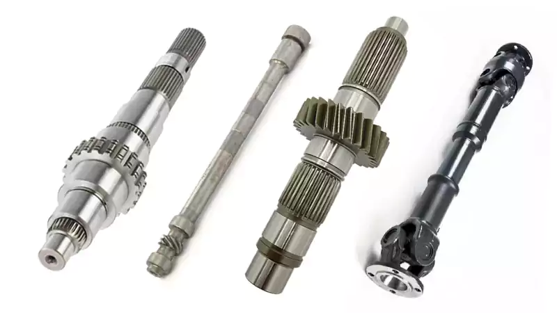
Common Shaft Types
- Solid shafts for high torque and stiffness3
- Hollow shafts for weight reduction
- Stepped shafts for bearing and gear seats
- Splined shafts for torque transfer
Typical Application Areas
| Industry | Key Requirements |
|---|---|
| Automotive | Fatigue strength, cost control |
| Aerospace & defense | Weight, certification, traceability |
| Power & energy | Long life, torsional stability |
| Industrial equipment | Flexibility, repeatability |
Each application changes tolerance focus and inspection strategy.
Materials and Mechanical Requirements for Transmission Shafts?
Material choice defines how forgiving a shaft will be during machining and in service. I never select material by strength alone.
Transmission shaft materials must balance strength, fatigue resistance, machinability, and heat treatment compatibility.

In Europe and global markets, I often see engineers specify very strong alloys without considering distortion risk. Strong material does not always mean stable machining.
Common Materials Used
| Material | Typical Use |
|---|---|
| Carbon steel4 (C45) | General industrial shafts |
| Alloy steel (42CrMo4) | Automotive, power transmission |
| Stainless steel | Corrosion environments |
| Titanium alloys | Aerospace weight reduction |
Heat treatment changes everything. After quenching or carburizing, shafts often move. I always plan grinding or finish turning after heat treatment to regain accuracy.
Manufacturing Processes for Precision Transmission Shafts?
Manufacturing decides whether the design works in real life. A good drawing can still fail with the wrong process flow.
Precision transmission shafts rely on controlled CNC turning, milling, grinding, heat treatment, and inspection as a connected process.

I plan shaft manufacturing as a sequence, not as isolated steps.
Typical Process Flow
- CNC turning for rough shape
- Milling for keyways or splines
- Heat treatment for strength
- CNC grinding for final size
- Inspection and balance check
Case Study: Automotive Gearbox Transmission Shaft
| Parameter | Value |
|---|---|
| Material | 42CrMo4 |
| Length | 420 mm |
| Max diameter | 55 mm |
| Tolerance | ±0.008 mm |
| Heat treatment | Quenched & tempered |
| Final process | Cylindrical grinding5 |
This project reduced vibration by 20% after switching from finish turning to grinding. Cycle time increased slightly, but warranty risk dropped sharply.
How to Customize Transmission Shafts for Your Application?
Customization starts before quoting. Many problems appear because key information is missing at RFQ stage.
Custom transmission shafts require clear definition of load, tolerance, volume, and inspection needs so the machining process can be optimized from the start.

When I review a custom shaft request, I focus on function first. Geometry comes second.
Information That Matters Most
| Input | Why It Is Important |
|---|---|
| Torque and speed | Sets base design |
| Bearing and fit type | Defines tolerance |
| Annual volume | Affects process choice |
| Certification needs | Drives inspection depth |
I often advise buyers to let the machining supplier suggest process changes. Small design adjustments can reduce cost without changing function.
Conclusion
Transmission shafts demand careful design and controlled CNC manufacturing. When material, process, and application align early, reliability improves and total cost drops.

-
Understand the definition and applications of automotive torque. ↩
-
Exploring load cycles helps in predicting fatigue life, which is essential for durability and reliability in design. ↩
-
Explore this link to understand how solid shafts enhance performance in high torque scenarios, ensuring reliability and efficiency. ↩
-
Understand what carbon steel is, its advantages, and common grades. ↩
-
Explore this link to understand how cylindrical grinding enhances precision and reduces vibration in manufacturing processes. ↩
