Are your machined parts failing at final assembly, even when they seem to be in spec? Simple plus/minus tolerances can't define complex part relationships, leading to fitment issues.
Geometric Dimensioning and Tolerancing (GD&T) is a symbolic language used on engineering drawings to define the allowable variation in a part's geometry. It ensures parts fit and function correctly.
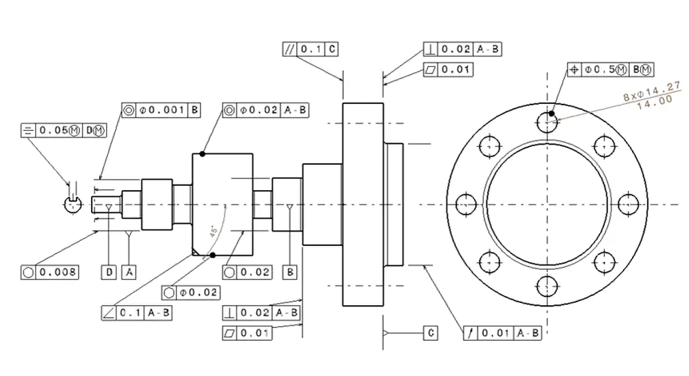
As a machinist, the first thing I look at on a new drawing are the GD&T callouts. This is where the true design intent is communicated. For an engineer like David, who designs complex robotic systems, GD&T is the language that guarantees all his custom components will assemble and function as a system. At my shop, we interpret these symbols every day when processing drawings. It's a skill that's absolutely critical to what we do. My experience tells us that correctly understanding GD&T can prevent 70% of assembly problems It moves beyond simple dimensions to control the relationships between features, and mastering this language is the key to successful precision manufacturing.
What is GD&T and Why Does It Matter?
What are all those strange symbols and boxes on engineering drawings? Why is GD&T so important for modern manufacturing and engineering?
GD&T is a precise language that uses universal symbols to control a part's features. It matters because it eliminates ambiguity, ensures interchangeability of parts, and guarantees proper assembly and function.
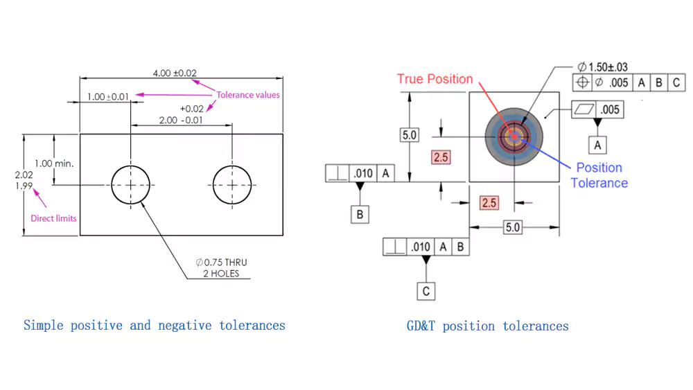
Diving Deeper into the Importance of GD&T
Geometric Dimensioning and Tolerancing (GD&T)1 is a system of symbols, rules, and definitions used to describe the geometry of manufactured parts. Think of it as a universal language that allows a designer like David to communicate his exact requirements to a machinist like me, anywhere in the world, without any misunderstanding.
Its importance in modern manufacturing cannot be overstated. Here’s why it matters so much:
- It Describes Function: GD&T is based on how the part actually functions. Instead of just controlling the size of a hole, it controls the location of the axis of that hole relative to other features. This ensures that when a bolt passes through a series of holes on mating parts, they will actually line up.
- It Eliminates Ambiguity: Traditional plus/minus tolerancing can be ambiguous. Does a tolerance on a flat surface control its waviness, or its angle? GD&T uses specific symbols for specific controls (like flatness or angularity), so there is no guesswork. Everyone is on the same page.
- It Improves Quality and Reduces Waste: By defining the exact tolerance requirements based on function, GD&T ensures that parts that meet the drawing's specifications will always work. It also prevents parts from being rejected for variations that don't actually affect function, which saves time and money.
- It Enables Universal Interchangeability: In a global supply chain, parts for an assembly might be made in different factories around the world. GD&T provides a single, consistent standard that guarantees all these parts will fit together seamlessly during final assembly.
In short, GD&T is the foundation of modern precision manufacturing. It is the language that makes complex mechanical systems possible.
What Are the 4 Main Categories of GD&T Symbols?
How are the various GD&T symbols organized? What are the main groups of geometric controls that engineers use to define a part's features?
The 14 primary GD&T symbols are organized into four main categories based on the type of tolerance they control: form, orientation, location, and runout. Each category addresses a different aspect of the part's geometry.

Diving Deeper into the GD&T Categories
The GD&T system is built around a logical hierarchy of controls. These controls are grouped into four distinct categories that build upon each other, from the shape of a single surface to the complex relationship between multiple rotating features. For David, selecting symbols from these categories allows him to precisely control every aspect of his design.
Here are the four main categories:
-
- Purpose: These are the most basic controls. They define the shape of an individual feature, independent of any other feature. They do not use a datum.
- Symbols: Straightness, Flatness, Circularity (Roundness), and Cylindricity.
- Example: A flatness callout ensures that a single surface is flat within a certain limit, regardless of how that surface is oriented to the rest of the part.
-
Orientation Tolerances:
- Purpose: These controls define the angle or orientation of a feature relative to another feature or datum. They always require a datum reference.
- Symbols: Angularity, Perpendicularity (Squareness), and Parallelism.
- Example: A perpendicularity callout ensures that one surface is 90 degrees to a datum surface within a specified tolerance.
-
Location Tolerances:
- Purpose: These are some of the most powerful controls. They define the location of a feature relative to other features or datums.
- Symbols: Position, Concentricity, and Symmetry.
- Example: The Position (or True Position) tolerance is used to control the location of a hole's axis, ensuring it's in the perfect spot for a bolt to pass through.
-
Runout Tolerances:
- Purpose: These controls are used for rotating parts. They define how much a feature can vary with respect to a datum axis as the part is rotated.
- Symbols: Circular Runout and Total Runout.
- Example: A runout callout on a shaft ensures it spins smoothly without wobbling.
What Are the Form Tolerances?
How do you control the basic shape of a feature? What are the GD&T symbols that define the form of a flat surface or a cylinder?
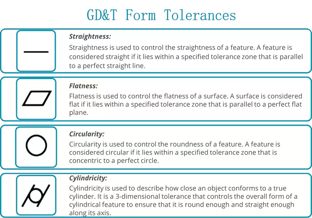
Form tolerances control the shape of a feature itself. The symbols are straightness, flatness, circularity, and cylindricity. They are unique because they do not require a datum reference.
Diving Deeper into Form Controls
Form tolerances are the foundation of geometric control. They are applied to a single feature and do not relate it to any other part of the component. They answer the simple question: "Is this feature the shape it's supposed to be?"
Here are the four form tolerances:
- Straightness:
- Symbol: — (a single straight line)
- What it Controls: The variation of a surface or an axis from a perfect straight line. When applied to a surface, it controls line elements on that surface. When applied to a cylindrical feature's size dimension, it controls the straightness of the central axis.
- Flatness:
- Symbol: ⏥ (a parallelogram)
- What it Controls: How much a single surface can vary from a perfect plane. The tolerance zone is defined by two parallel planes. The entire surface must lie between these two planes. This is a much tighter control than just a plus/minus tolerance on the surface's dimension.
- Circularity (or Roundness):
- Symbol: ○ (a circle)
- What it Controls: How close a circular feature is to a perfect circle. When measuring any 2D cross-section of a shaft or hole, all points on the circumference must lie between two concentric circles.
- Cylindricity3:
- Symbol: ⌭ (a circle with two tangent lines)
- What it Controls: This is a 3D control that combines circularity and straightness. It ensures that a cylindrical feature is both round and straight along its entire length. The tolerance zone is defined by two concentric cylinders. All points on the surface must lie within this zone. This is one of the most demanding form controls.
What Are the Orientation Tolerances?
How do you control the angle between two features? What are the GD&T symbols used to ensure two surfaces are perfectly parallel or perpendicular?
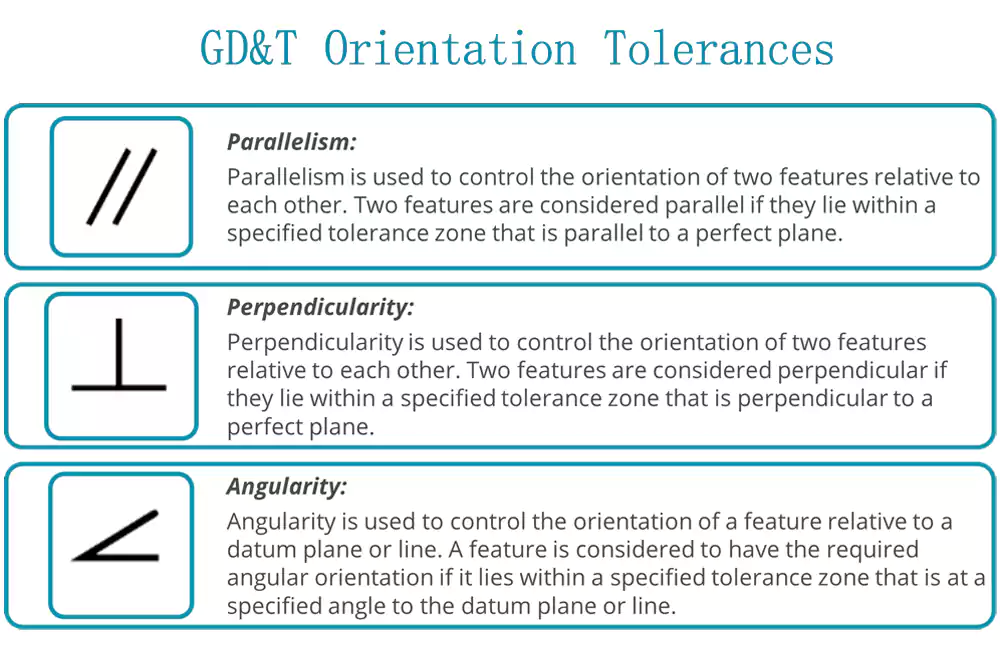
Orientation tolerances control the angle of a feature relative to a datum. The symbols are parallelism, perpendicularity, and angularity. They are essential for ensuring parts mate correctly.
Diving Deeper into Orientation Controls
Once the form of individual features is controlled, the next step is to control their relationship to each other. Orientation tolerances control the tilt or angle of features. They always require a datum—a theoretically perfect point, line, or plane that serves as a reference.
Here are the three orientation tolerances4:
- Parallelism:
- Symbol: ∥ (two parallel lines)
- What it Controls: The condition of a surface or axis being equidistant at all points from a datum plane or axis. The tolerance zone is defined by two parallel planes or a cylinder that are perfectly parallel to the datum.
- Example: Ensuring the top surface of a block is parallel to the bottom surface (the datum).
- Perpendicularity (or Squareness):
- Symbol: ⊥ (a perpendicular line symbol)
- What it Controls: The condition of a surface or axis being at a perfect 90-degree angle to a datum plane or axis. The tolerance zone is defined by two parallel planes that are exactly 90 degrees to the datum.
- Example: Ensuring the side of a block is perfectly square to the bottom surface.
- Angularity:
- Symbol: ∠ (an angle symbol)
- What it Controls: The condition of a surface or axis being at any specified angle (other than 90 degrees) relative to a datum. The tolerance zone is defined by two parallel planes that are at the specified basic angle from the datum.
- Example: Ensuring a surface on a wedge block is at a perfect 45-degree angle to the base.
For an engineer like David, these controls are critical for making sure that parts that are bolted together sit flush and that components that slide against each other do so smoothly.
What Are the Location Tolerances?
How do you control the exact location of a critical feature, like a hole in a bolt pattern? What are the most important GD&T symbols for positioning?
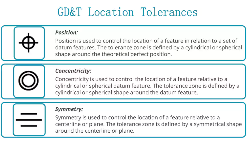
Location tolerances control the position of features relative to datums or other features. The primary symbols are position (true position), concentricity, and symmetry. Position is the most widely used.
Diving Deeper into Location Controls
Location tolerances are arguably the most powerful and important in the GD&T system. They define the exact location of features, which is fundamental to ensuring that parts in an assembly fit together.
Here are the three location tolerances:
- Position (or True Position):
- Symbol: ⌖ (a crosshair symbol)
- What it Controls: This is the most common GD&T control. It defines a tolerance zone within which the axis or center plane of a feature of size (like a hole, pin, or slot) is permitted to vary from its "true position." The true position is the theoretically exact location of the feature, defined by basic dimensions on the drawing.
- Why it's better: Unlike plus/minus tolerancing which creates a square tolerance zone, true position creates a cylindrical tolerance zone for a hole's axis. This more accurately reflects how parts function and provides a larger, more realistic tolerance zone for the machinist. It is essential for bolt patterns.
- Concentricity:
- Symbol: ◎ (two concentric circles)
- What it Controls: The relationship between the axes of two or more cylindrical features that share a common axis. It requires that the median points of the controlled feature's cross-sections lie within a cylindrical tolerance zone that is perfectly coaxial with the datum axis. It is a very demanding and difficult tolerance to inspect.
- Symmetry:
- Symbol: ⌯ (three horizontal lines)
- What it Controls: The condition where the median plane of a feature is congruent with the median plane of a datum feature. It ensures that a feature is perfectly centered about a datum plane. Like concentricity, it is difficult to inspect and is less common in modern drawings.
For an engineer like David, the True Position tolerance is the most important tool for ensuring that all the bolt holes on his custom parts line up perfectly during assembly.
What Are the Runout Tolerances?
How do you control the "wobble" of a rotating part? What GD&T symbols are used to ensure that a shaft or other cylindrical component spins smoothly and accurately?
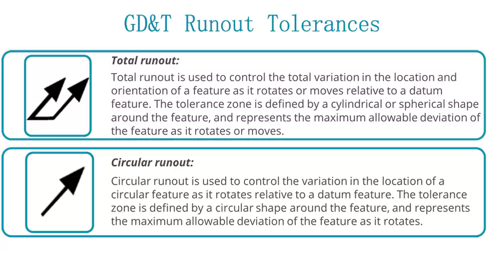
Runout tolerances control the variation of a surface as a part is rotated around a datum axis. The two symbols are circular runout and total runout, used for rotating components.
Diving Deeper into Runout Controls
Runout tolerances are specifically designed for parts that rotate, like shafts, axles, and gears. They control a combination of form and location errors (like roundness and concentricity) with a single, simple measurement. This is a very practical and functional type of tolerance.
Here are the two runout tolerances:
- Circular Runout:
- Symbol: ↗ (a single arrow)
- What it Controls: The variation of individual circular elements of a surface as the part is rotated 360 degrees about a datum axis. It is a 2D control. To measure it, a dial indicator is placed on the surface, and the part is rotated. The total movement of the indicator's needle must be within the specified tolerance. It controls the combined effects of circularity and concentricity at that specific cross-section.
- Total Runout:
- Symbol: ≯ (two arrows)
- What it Controls: This is a much more comprehensive 3D control. It controls the variation of the entire surface as the part is rotated about the datum axis. To measure it, the dial indicator is moved along the full length of the surface as the part rotates. The total movement of the needle must be within the tolerance. It controls the combined effects of circularity, straightness, concentricity, and taper of the entire surface. This is a very stringent control used for critical rotating parts.
For David's work in robotics and automation, runout tolerances are essential for ensuring that shafts for motors and bearings spin true, which is critical for smooth operation and long service life.
What Is the GD&T Symbol Reference Table?
With so many symbols, how can you keep them all straight? Is there a quick reference table that lists all the main GD&T symbols and their meanings?
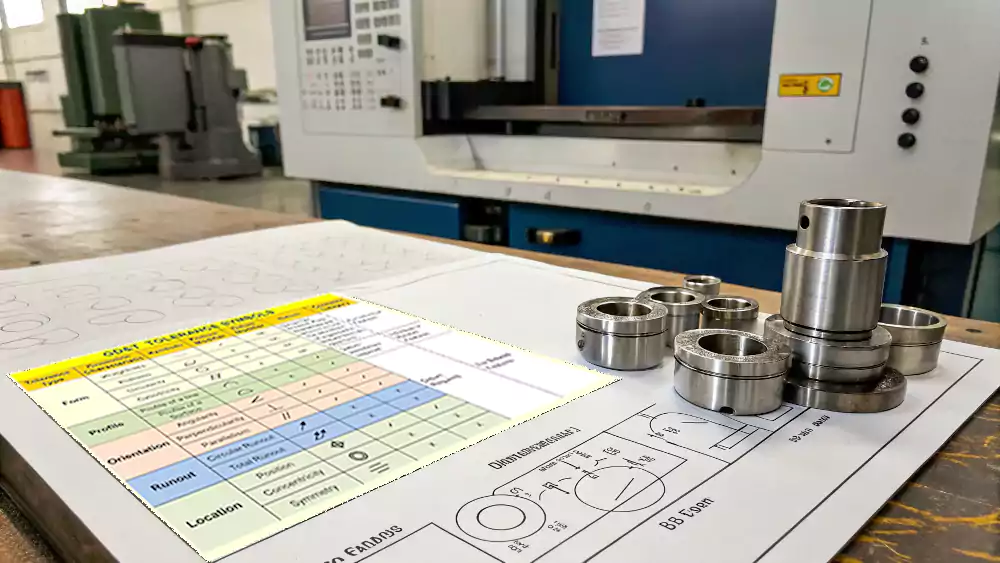
Yes, a GD&T reference table organizes the 14 main symbols by their category (form, orientation, location, runout) and provides the name and function for each symbol in a clear, easy-to-read format.
Diving Deeper into a Quick Reference
Having a simple reference table is the best way to quickly identify and understand the GD&T symbols on a drawing. Here is a summary of the 14 primary geometric characteristic symbols.
| Category | Symbol | Name | What It Controls |
|---|---|---|---|
| Form | — | Straightness | The "straightness" of a line element or axis. |
| ⏥ | Flatness | The "flatness" of a single surface. | |
| ○ | Circularity | The "roundness" of a 2D cross-section. | |
| ⌭ | Cylindricity | The "roundness" and "straightness" of an entire cylinder. | |
| Orientation | ∥ | Parallelism | The "parallelness" of a feature to a datum. |
| ⊥ | Perpendicularity | The "squareness" (90°) of a feature to a datum. | |
| ∠ | Angularity | The specified angle of a feature to a datum. | |
| Location | ⌖ | Position | The location of a feature's axis or center plane. |
| ◎ | Concentricity | The coaxiality of the axes of two cylinders. | |
| ⌯ | Symmetry | The centeredness of a feature about a datum plane. | |
| Runout | ↗ | Circular Runout | The variation of a single circular element during rotation. |
| ≯ | Total Runout | The variation of an entire surface during rotation. | |
| Profile | ⌒ | Profile of a Line | The 2D profile of a complex curve or shape. |
| ⌓ | Profile of a Surface | The 3D profile of a complex surface. |
Note: The profile tolerances can control form, orientation, and location, so they are sometimes considered their own category.
What Are the Associated Symbols & Feature Control Frames?
What are all the other boxes and symbols that go with the main GD&T callouts? How do you read the entire block of information on a drawing?
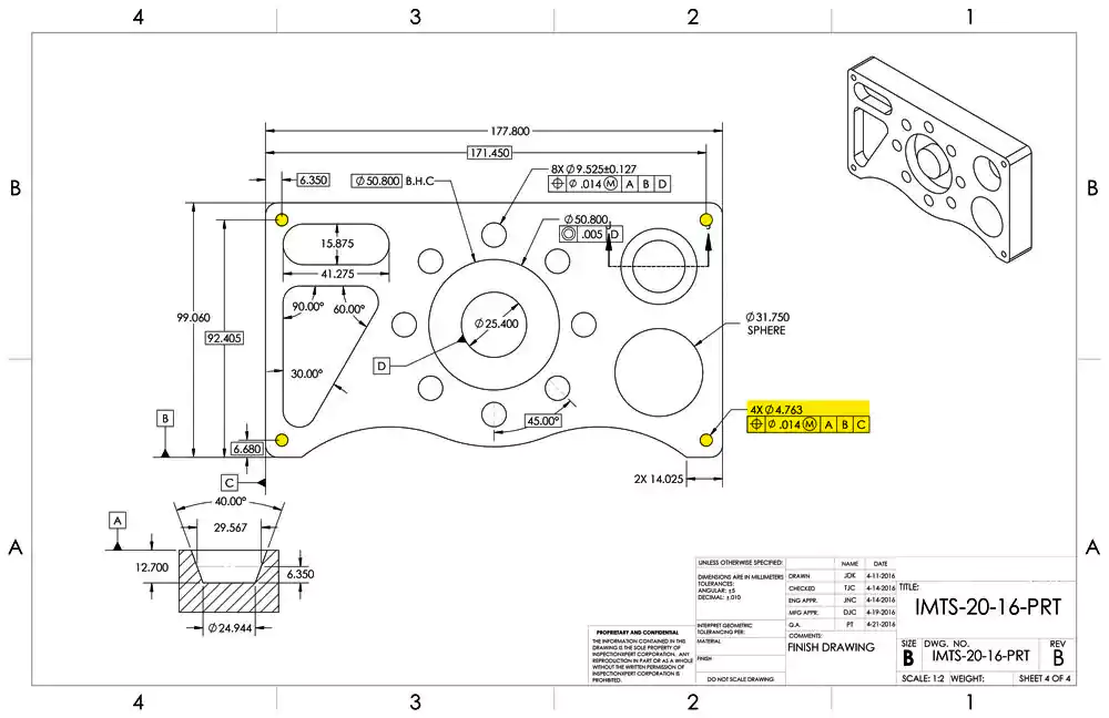
The Feature Control Frame is the rectangular box that contains the complete GD&T instruction. It includes the geometric symbol, the tolerance value, and any necessary datum references or modifiers.
Diving Deeper into GD&T Syntax
The main geometric symbol is just one part of a complete GD&T instruction. The entire instruction is contained within a rectangular box called the Feature Control Frame5. Reading this frame from left to right is like reading a sentence.
Here's how to break it down:
- Geometric Characteristic Symbol: The first compartment always contains one of the 14 main symbols (e.g., ⌖ for Position). This states what is being controlled.
- Tolerance Value: The second compartment contains the total tolerance value. It is often preceded by a diameter symbol (⌀) if the tolerance zone is cylindrical (like for a Position tolerance). This states how much the feature can vary.
- Modifiers: After the tolerance value, you may see a material condition modifier. These are critical symbols:
- Ⓜ (Maximum Material Condition - MMC6): This modifier means the stated tolerance applies when the feature is at its largest size (e.g., smallest hole or largest pin). It allows for a "bonus tolerance" as the feature departs from its MMC size.
- Ⓛ (Least Material Condition - LMC): This is the opposite of MMC. The tolerance applies when the feature is at its smallest size.
- Datum References: The remaining compartments list the datum references in order of precedence (Primary, Secondary, Tertiary). These are letters (e.g., A, B, C) that relate the controlled feature to the part's datum reference frame. This states what the feature is being controlled in relation to.
For example, a Feature Control Frame for a hole might read: [⌖ | ⌀0.1 Ⓜ | A | B | C]. This translates to: "The true position of this hole's axis must be within a cylindrical tolerance zone of 0.1mm at its Maximum Material Condition, relative to datums A, B, and C."
What Are Tolerance Zones Explained?
What does a GD&T tolerance actually look like? How is a "tolerance zone" different from a simple plus/minus dimension?
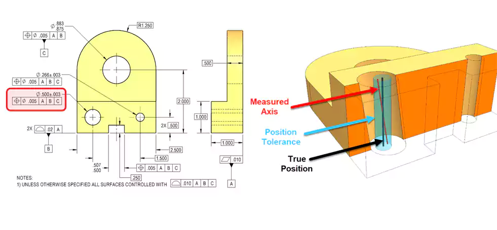
A tolerance zone is the 3D space within which a feature is allowed to exist. Unlike a 2D plus/minus tolerance, a GD&T zone defines the shape, size, and location of this space.
Diving Deeper into the Concept of Zones
The concept of the tolerance zone is perhaps the biggest and most important difference between GD&T and traditional plus/minus tolerancing. For an engineer, thinking in terms of 3D zones is key to understanding the power of GD&T.
Traditional Plus/Minus Tolerancing
Let's take the location of a hole. A traditional drawing might locate a hole with an X and Y dimension, each with a tolerance like ±0.1. This creates a square tolerance zone that is 0.2 x 0.2. The axis of the hole must lie within this square.
GD&T True Position Tolerancing
GD&T, on the other hand, locates the hole with basic dimensions (theoretically exact numbers in boxes) and then applies a Position tolerance. This creates a cylindrical tolerance zone for the axis of the hole to lie within.
Why is a Cylindrical Zone Better?
A cylindrical tolerance zone is better for a round hole because it more accurately reflects how the part functions. A bolt is round, so the hole's location can vary equally in any direction from the center.
- More Usable Tolerance: The area of a round tolerance zone is about 57% larger than the area of a square zone with the same "size." This means GD&T provides a larger, more realistic target for the machinist, which can make the part easier and cheaper to produce without sacrificing function.
- Shape of the Zone: GD&T defines the shape of the zone. For a Flatness callout, the zone is two parallel planes. For a Perpendicularity callout, the zone is two parallel planes that are perfectly 90 degrees to a datum. This level of specific control is impossible with plus/minus dimensions.
Thinking in terms of these virtual 3D zones is fundamental to both designing with and inspecting to GD&T.
What Are the Practical Applications of GD&T in CNC Machining?
How does a machinist actually use GD&T? How do these symbols on a drawing translate into the real-world process of CNC machining and inspection?
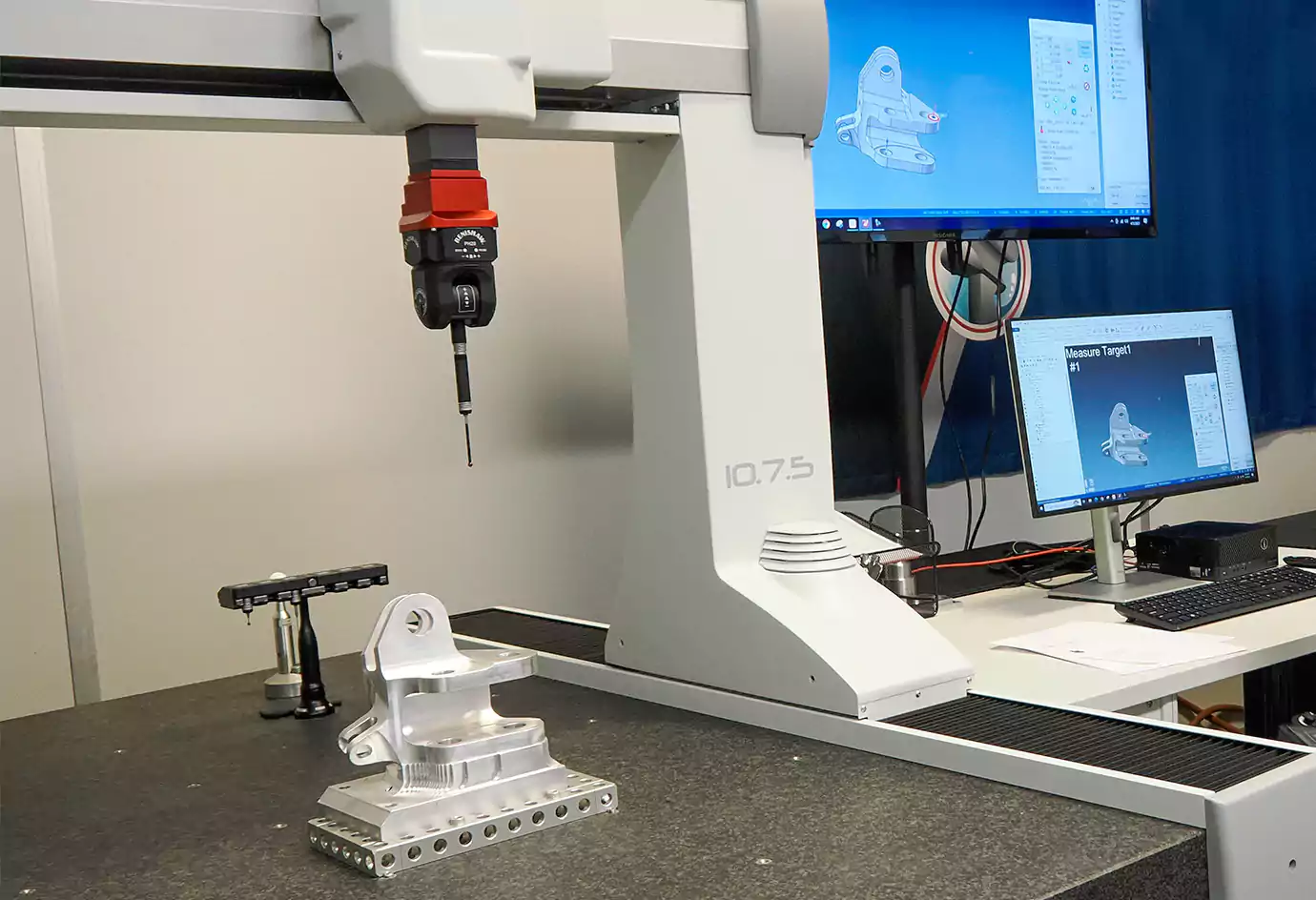
In CNC machining, GD&T directly informs the manufacturing strategy. A true position callout dictates the required machine accuracy, while a flatness callout might require a special finishing pass.
Diving Deeper into Shop Floor Application
As a machinist, GD&T is not just a theoretical concept; it's my instruction manual for making the part correctly. The symbols and numbers tell me which features are critical and how they must relate to each other. This directly impacts how I plan the job.
Here are some practical examples of how GD&T is applied:
-
True Position of a Bolt Pattern:
- When David puts a true position tolerance on a set of holes, it tells me that their location relative to each other and to the datums is critical.
- Machining Strategy: I know I must machine this entire pattern in a single setup on a high-precision CNC mill to ensure their locations are accurate. I cannot machine one hole, then re-clamp the part and machine another, as that would introduce error.
- Inspection: It also tells me I cannot just check the X and Y coordinates of the holes. I need to use a Coordinate Measuring Machine (CMM) to measure the true position of each hole's axis and verify it's within the specified cylindrical tolerance zone.
-
Flatness or Parallelism of a Surface:
- If a surface has a very tight flatness or parallelism callout, it tells me that a standard milling pass might not be good enough.
- Machining Strategy: I might need to use a special face mill, take very light finishing passes, or even move the part to a surface grinder after milling to achieve the required level of precision.
-
- A tight total runout tolerance tells me the shaft must be perfectly straight and concentric.
- Machining Strategy: I will likely turn the shaft between centers on a CNC lathe and then transfer it to a cylindrical grinder for a final finishing pass to ensure everything is perfectly aligned to the central datum axis.
GD&T dictates the required machine tools, the machining strategy, and the inspection methods needed to produce a conforming part.
How Do Case Studies Show GD&T Ensuring Fit and Function?
Can we see a real-world example? How does applying GD&T solve a practical assembly problem that simple tolerances cannot?
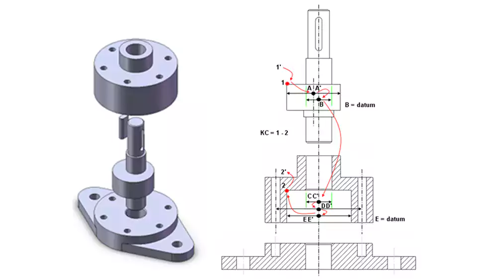
A case study of a shaft and housing assembly shows how GD&T ensures a perfect fit. Runout on the shaft and true position on the housing's bolt holes guarantee alignment.
Diving Deeper with Practical Case Studies
The best way to understand the power of GD&T is to see how it solves real-world problems. Let's look at two simple case studies that an engineer like David would encounter.
Case Study 1: The Motor Mount Plate
- Problem: A company is making a simple mounting plate with four holes to attach a motor. The drawing uses plus/minus tolerances (±0.1mm) for the hole locations. Some plates work fine, but others cause the motor shaft to bind because the holes don't line up perfectly.
- Analysis: The square tolerance zones of the ± dimensions allow for a combination of errors that results in a misaligned pattern, even though each individual hole is "in spec."
- GD&T Solution: The engineer, David, redesigns the drawing. He defines the hole locations with basic dimensions and applies a single True Position tolerance of ⌀0.2mm to all four holes, referencing the part's edges as datums.
- Result: The new callout ensures that the entire pattern of holes is located correctly. It guarantees that if a plate passes inspection, any motor will fit perfectly every time. This solves the assembly problem completely.
Case Study 2: The High-Speed Shaft and Seal
- Problem: A high-speed shaft passes through a housing with a rubber lip seal. The company finds that some seals wear out and leak very quickly.
- Analysis: Measuring the shaft shows its diameter is within tolerance. However, the shaft has a slight "wobble" as it spins, which is causing the seal lip to wear down prematurely. Simple dimensional tolerances don't control this.
- GD&T Solution: David adds a Total Runout tolerance to the shaft surface that contacts the seal, referencing the bearing journals as the datum axis.
- Result: This new requirement forces the manufacturing process to be more controlled (likely requiring grinding). The resulting shafts are much straighter and more concentric to the axis of rotation. They spin true, the wobble is eliminated, and the seal life increases dramatically.
These examples show how GD&T moves beyond simple size control to ensure the functional relationships between features are maintained, which is the key to successful mechanical assemblies.
Conclusion
GD&T is the universal language of precision manufacturing. Mastering its symbols and principles is essential for designing and producing parts that fit and function perfectly every time.If you encounter GD&T challenges when designing parts, we can help you evaluate manufacturability and provide the optimal machining solution. Click to contact us!
-
Explore this link to understand GD&T's critical role in ensuring precision and clarity in manufacturing processes. ↩
-
Understanding Form Tolerances is crucial for precise design control, ensuring features maintain their intended shape. ↩
-
Exploring cylindricity helps grasp its importance in ensuring cylindrical features are both round and straight, vital for quality control. ↩
-
Exploring orientation tolerances will enhance your knowledge of how to maintain proper alignment and fit in mechanical assemblies, crucial for quality control. ↩
-
Understanding the Feature Control Frame is essential for interpreting GD&T instructions accurately. ↩
-
Exploring MMC will enhance your knowledge of tolerancing and its impact on manufacturing processes. ↩
-
Exploring Total Runout helps grasp its impact on shaft performance and the necessary machining techniques for accuracy. ↩

