Custom automotive shafts often fail early because design, material, or process choices were wrong from the start. I have seen projects delayed and budgets wasted due to small early mistakes.
Custom automotive shaft machining is the process of manufacturing high-precision rotating or load-bearing shafts for vehicle systems using CNC turning, milling, grinding, and heat treatment to meet strict OEM performance and tolerance standards.
Every shaft project looks simple on a drawing. In real production, small details decide service life, noise levels, and safety margins. I want to walk through how I approach these parts from an engineering and sourcing view. If you need a broader overview first, I usually point engineers to our complete custom shaft manufacturing guide for background on materials, processes, and design logic.
What Is a Custom Automotive Shaft and Where Is It Used?
Many buyers think a shaft is just a round bar with steps. That idea leads to wrong suppliers and short part life.
A custom automotive shaft is a precision-machined rotating component designed for specific torque, alignment, and durability requirements in systems like transmissions, steering columns, and electric drive units.
When I review drawings from OEM or Tier suppliers, I first look at function, not shape. A shaft may transmit torque, locate bearings, carry gears, or connect steering joints. Each job changes tolerance strategy and material choice. For teams new to rotating components, I sometimes suggest reading a basic explanation of what a motor shaft is since many design principles overlap.
Definition of Precision Automotive Shafts
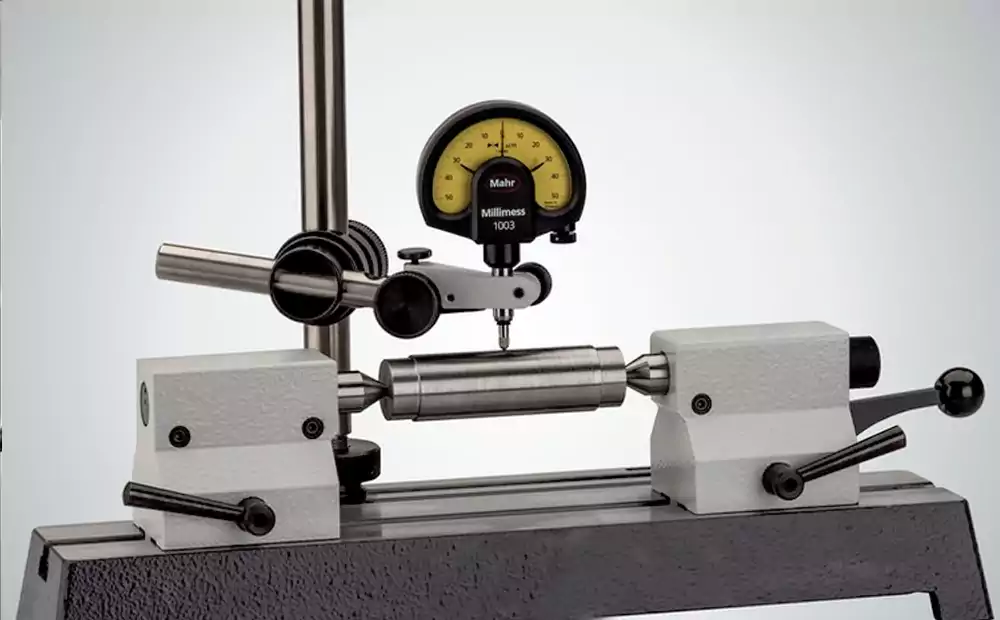
These shafts control motion and power flow. Runout, concentricity, and surface finish1 affect vibration and wear. Even a 0.01 mm error can change bearing life.
Why Standard Shafts No Longer Meet Modern Vehicle Requirements
Modern vehicles use higher speeds and lighter designs. EV drivetrains run at very high RPM2. Downsized engines push higher torque through smaller parts. Off-the-shelf shafts rarely match these mixed demands.
Applications in Powertrain, Transmission & Steering Systems
| System | Shaft Function | Key Risk if Poorly Made |
|---|---|---|
| Transmission | Transfers torque between gears | Noise, premature wear |
| EV Drive | High-speed rotor or output shaft | Imbalance, overheating |
| Steering | Connects steering input to rack | Vibration, safety issues |
For a deeper technical look at gearbox-related parts, I often reference this breakdown of transmission shafts when discussing load paths and spline design.
I always confirm the system role before quoting. This step avoids costly redesign later.
What Types of Automotive Shafts Exist and What Performance Do They Need?
Engineers focus on stress and alignment. Buyers focus on reliability and repeatability. Both meet in performance targets.
Automotive shafts vary by function—transmission, drive, steering—and must meet defined limits for torsional strength, fatigue life, runout, surface hardness, and weight to ensure long service life under dynamic loads.
I group shafts by how they are loaded. Some see constant rotation. Some see shock loads. Some must stay very straight over long lengths.
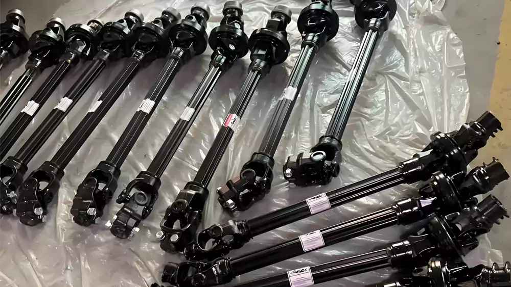
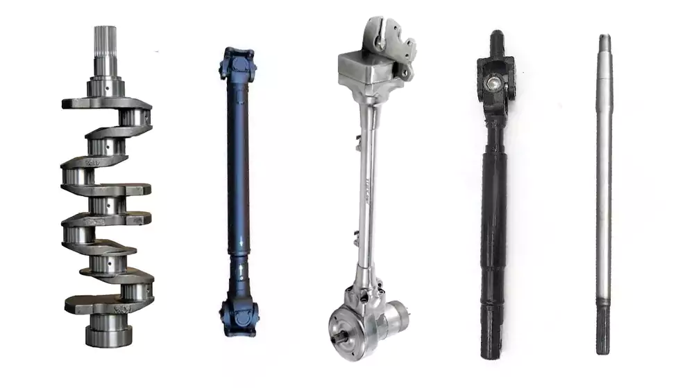
Common Shaft Types We Machine
- Transmission input and output shafts
- Counter shafts with multiple gear seats
- Splined drive shafts
- Steering intermediate shafts
Each type changes machining sequence and inspection points.
Key Performance Requirements for OEM Shafts
| Requirement | Why It Matters | Typical Control Method |
|---|---|---|
| Torsional strength3 | Prevents twisting failure | Material + heat treatment |
| Fatigue resistance | Long life under cyclic loads | Fillet design + surface finish |
| Concentricity | Reduces vibration and noise | Precision turning + grinding |
| Surface wear resistance | Protects bearing and seal areas | Induction hardening, nitriding |
| Weight optimization4 | Helps fuel economy / EV efficiency | Alloy choice, hollow designs |
When I talk with procurement teams, I explain that these targets often force custom work. Standard bar stock and basic turning are not enough.
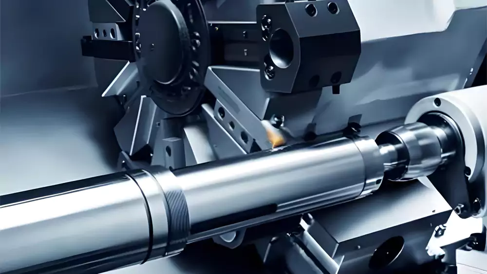
How Are Automotive Shafts Machined and What Materials Are Used?
Many suppliers can turn a shaft. Fewer can hold tight runout after heat treatment. Process chain control is key.
Automotive shafts are produced through multi-step CNC turning, milling, spline cutting, precision grinding, and controlled heat treatment using alloy steels or specialty materials chosen for strength, wear resistance, and stability.
I plan shaft machining like a sequence, not single operations. For readers who want a process-focused overview, our page on CNC machining of shafts explains operation order and tolerance strategy in more detail.
CNC Turning for Stepped Profiles and Shoulders
Turning creates main diameters, shoulders, and grooves. Tool path stability affects roundness and size control.
Milling, Keyways and Spline Machining
Splines and keyways transmit torque. Profile accuracy affects load sharing. I prefer dedicated spline tooling or gear hobbing for repeat work.
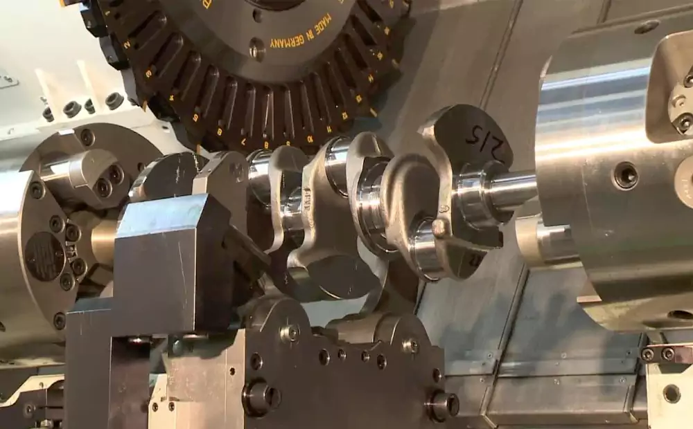
Precision Grinding for Bearing Seats and Tight Tolerances
Grinding is often the last step. It corrects distortion and brings bearing journals into final tolerance.
Heat Treatment and Surface Hardening
| Method | Typical Use | Benefit |
|---|---|---|
| Induction hardening | Bearing seats, spline areas | Local wear resistance |
| Carburizing | Transmission shafts | Hard surface, tough core |
| Nitriding | Precision shafts with low distortion | Hard surface, minimal growth |
Common Materials Used
- 4140 and 4340 alloy steels for high strength
- 8620 for carburized transmission shafts
- Stainless steels for corrosion resistance
- Lightweight alloys for some EV components
Material choice links directly to heat treatment and machining allowance planning.
How Do We Control Quality, Tolerances, and Manufacturing Challenges?
Most shaft problems appear after heat treatment. That is where real process control shows.
Quality control for automotive shafts focuses on tight IT-grade tolerances, runout and straightness control, in-process gauging, and managing distortion from heat treatment to ensure repeatable performance in mass production.
I build inspection into each stage, not only at the end.
Typical Tolerances for Automotive Shafts
Bearing seats often fall in IT5–IT6 range. Runout can be under 0.01 mm on critical journals.
Controlling Runout, Straightness and Concentricity
We use soft jaws, steady rests, and between-center grinding. Process sequence matters more than machine brand.
Inspection Methods
| Tool / Method | Purpose |
|---|---|
| CMM | Position and geometry checks |
| Roundness tester | Roundness and cylindricity |
| In-process gauging | Diameter control during turning |
| Hardness tester | Verifies heat treatment results |
Case Study: Transmission Output Shaft
I worked on a shaft for a light truck transmission program.
| Parameter | Value |
|---|---|
| Material | 8620 alloy steel |
| Heat treatment | Carburized, 58–62 HRC surface |
| Overall length | 312 mm |
| Max diameter | 48 mm |
| Bearing seat tolerance | Ø35 h6 (0 / -0.013 mm) |
| Runout requirement | ≤0.008 mm |
| Annual volume | 85,000 pcs |
Early samples failed runout after heat treatment. We changed stock allowance and added semi-finish grinding before carburizing. Final rejection rate dropped below 0.6%. That project taught me that distortion planning must start at the drawing review stage.
How Does Global Sourcing Work and How Do We Support OEM Programs?
Choosing a supplier is not only about price. It is about process depth and long-term stability.
Global sourcing for automotive shafts balances cost, multi-axis machining capability, and the ability to support prototypes through mass production while maintaining automotive-level quality systems and engineering communication.
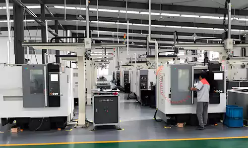
I often support customers who split sourcing between local and overseas partners. Many of them start from our central resource page for precision CNC shaft solutions to compare capabilities and applications.
Overseas CNC Sourcing vs. Local Supply
| Factor | Overseas CNC Supplier | Local Supplier |
|---|---|---|
| Cost | Lower for complex machining | Higher but faster logistics |
| Capacity | Strong for large programs | Limited for surge demand |
| Engineering input | Growing, depends on supplier | Easier face-to-face |
How We Work with OEM & Tier Suppliers
I start with drawing review and DFM feedback. I point out tolerance risks and heat treatment distortion zones. We support prototype builds, PPAP documentation, and then stable long-term production.
Starting a Custom Shaft Project
I ask customers to include:
- 2D drawings with GD&T
- 3D models (STEP preferred)
- Material and heat treatment specs
- Annual volume forecast
Clear data shortens quote time and avoids later changes.
Conclusion
The real life of an automotive shaft starts long before machining begins. Correct shaft type definition, material choice, process planning, and supplier capability must align. When these decisions are made early and correctly, OEM and Tier programs gain longer service life, lower risk, and more stable, predictable mass production.
-
Explore how these factors critically influence vibration and wear, essential for understanding precision shaft quality. ↩
-
Learn about the unique demands on shafts in electric vehicles, crucial for modern automotive design and performance. ↩
-
Explore this link to understand how enhancing torsional strength prevents twisting failure, ensuring shaft durability and reliability. ↩
-
Learn why weight optimization is crucial for improving fuel economy and EV efficiency through advanced alloy choices and hollow designs. ↩
