Editor's Note: Last updated on May 18, 2026, by Lucy
CNC milling is everywhere in modern manufacturing. Still, many engineers and buyers are unsure how it works, when to use it, and how to design parts correctly for machining.
CNC milling is a computer-controlled manufacturing process that removes material from a solid block using rotating cutting tools to create precise parts with tight tolerances, complex geometries, and repeatable quality. It is widely used for prototypes, custom parts, and production components across aerospace, automotive, robotics, and medical industries.
Understanding CNC milling is not only about knowing how a machine cuts metal. It is also about knowing how design, materials, tolerances, and machine selection affect your final cost, lead time, and part quality. I have seen projects succeed or fail based on just one small design decision.
How Does CNC Milling Work?
Many people use CNC milling and CNC machining as if they mean the same thing. They are related, but not identical.
CNC milling is one type of CNC machining that uses rotating cutting tools to remove material from a fixed workpiece, while CNC machining is a broader term that includes milling, turning, drilling, grinding, and other automated manufacturing processes.

If you are still comparing processes, this guide on CNC milling vs turning explains where each method fits best.
CNC milling starts with a CAD model. This is the digital design created by an engineer. The model is then imported into CAM software, which converts the design into machine-readable toolpaths. These toolpaths define spindle speed, feed rate, cutting depth, and tool movement.
The machine then follows those instructions automatically.
A typical workflow looks like this:
| Step | Description |
|---|---|
| CAD Design | Build 2D or 3D part model |
| CAM Programming | Generate toolpaths and machining strategy |
| Material Setup | Clamp raw stock material |
| Machining | Machine executes cutting operations |
| Inspection | Verify dimensions and tolerances |
| Finishing | Surface treatment or post-processing |
This workflow is what allows CNC milling to achieve consistency and repeatability1. A manually machined part can vary depending on operator skill. CNC milling reduces that variability significantly.
This is why industries like aerospace, robotics, and medical devices rely heavily on it.
What Types of CNC Milling Machines Are Available?
Not all CNC milling machines are built the same. Machine configuration directly affects what geometry you can produce.
CNC milling machines are available in vertical, horizontal, 3-axis, 4-axis, and 5-axis configurations, each designed for different levels of complexity, production efficiency, and machining accuracy.

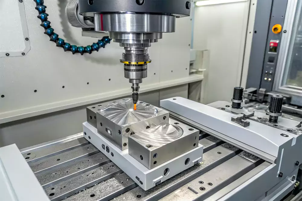
A vertical machining center is the most common setup. The spindle points downward, making it ideal for flat surfaces, pockets, drilling, and general machining.
Horizontal machines are better for larger parts and heavy material removal2. They also improve chip evacuation.
Machine capability comparison:
| Machine Type | Best For | Complexity |
|---|---|---|
| 3-Axis | Flat parts, brackets, housings | Low to medium |
| 4-Axis | Indexed machining, side features | Medium |
| 5-Axis | Complex geometry, aerospace parts | High |
A 3-axis machine moves in X, Y, and Z directions.
A 4-axis machine adds rotational movement, allowing more faces to be machined without repositioning.
A 5-axis machine adds two rotational axes. This allows cutting at nearly any angle.
Benefits of 5-axis machining:
- Fewer setups
- Better accuracy
- Faster cycle time
- Improved surface finish
- Ability to machine complex curved surfaces
For highly complex structures, this is where our custom CNC milling services become especially useful.
At Allied Metal, we regularly machine multi-angle robotic and automation components where 5-axis capability saves both time and cost.
What Materials, Tolerances, and Surface Finishes Can CNC Milling Handle?
Material choice changes everything in CNC milling, from cutting strategy to final part performance.
Common CNC milling materials include aluminum, stainless steel, titanium, brass, copper, ABS, POM, and PEEK. Standard tolerances are typically ±0.05 mm, while precision machining can achieve ±0.01 mm depending on geometry and material.

Material selection examples:
| Material | Advantages | Common Applications |
|---|---|---|
| Aluminum 6061 | Lightweight, easy machining | Housings, brackets |
| Stainless Steel 304 | Corrosion resistance | Medical, food equipment |
| Titanium Ti6Al4V | Strength, heat resistance | Aerospace |
| PEEK | Chemical resistance | Medical, electronics |
| ABS | Low cost, easy machining | Prototypes |
Surface finishing options include:
- Anodizing
- Sandblasting
- Powder coating
- Polishing
- Electroless nickel plating
- Black oxide
A raw machined part may meet dimensional requirements but still fail functional or cosmetic needs.
That is why finishing matters.
If you want a deeper technical breakdown, this article covers more CNC milling fundamentals.
How to Optimize CNC Milling Designs for Lower Cost and Better Manufacturability?
A well-designed part is easier and cheaper to machine.
A poorly designed part may still be manufacturable, but often costs much more.
Good CNC milling design follows manufacturability rules such as proper wall thickness, reasonable corner radii, standard hole depths, and simplified geometries to reduce machining time, tool wear, and production cost.

Common DFM guidelines:
| Feature | Recommended Rule |
|---|---|
| Minimum wall thickness | ≥ 0.8 mm metals |
| Internal corner radius | ≥ 1/3 cavity depth |
| Hole depth | ≤ 4× diameter |
| Thread depth | ≤ 3× diameter |
Design mistakes I see often:
- Extremely deep narrow pockets
- Sharp internal corners
- Excessively tight tolerances everywhere
- Non-standard threads
One small drawing adjustment can dramatically improve manufacturability.
This is why I always tell customers not to rush production.
Talk through the drawing first.
Sometimes changing one corner radius or wall thickness saves hours of machine time.
Where Is CNC Milling Used in Real Manufacturing Projects?
CNC milling is one of the most versatile manufacturing methods available.
CNC milling is widely used to manufacture precision components for aerospace, automotive, robotics, industrial automation, medical devices, electronics, and custom equipment production.

Typical CNC milling applications:
- Aerospace brackets
- Heat sinks
- Medical implants
- Robotic joints
- Automotive fixtures
- Electronic enclosures
Case Study: Precision Robotic Arm Joint
A robotics customer approached us with a joint housing that was difficult to machine due to multiple angled surfaces and tight tolerances.
Part details:
| Parameter | Specification |
|---|---|
| Material | Aluminum 7075 |
| Tolerance | ±0.02 mm |
| Surface Finish | Clear anodizing |
| Quantity | 120 pcs |
| Machine | 5-axis CNC milling |
| Lead Time | 9 days |
Challenges:
- Deep pocketing
- Tight concentricity
- Thin walls
Solution:
We optimized internal radii, increased wall thickness from 1.0 mm to 1.5 mm, and adjusted thread depth.
Results:
- Cost reduced by 18%
- Machining time reduced by 22%
- Part rigidity improved significantly
This is exactly why design review matters before production.
At Allied Metal, we can machine everything from simple brackets to highly complex multi-axis parts, whether you need one prototype or a full production run. My advice is always the same: do not rush into machining your first design without reviewing manufacturability first. A small design change can make your part easier to produce, more durable in use, and far more cost-effective.
Conclusion
CNC milling is more than just a cutting process. It is one of the most reliable and flexible manufacturing methods for turning digital designs into high-precision physical parts. From machine selection and material choice to tolerances, surface finishing, and DFM optimization, every decision affects the final quality, cost, and lead time.
Whether you are developing a prototype, scaling to production, or sourcing a complex custom component, understanding how CNC milling works helps you make better engineering and purchasing decisions. In my experience, the most successful projects are rarely the ones with the most complicated designs, but the ones where design intent and manufacturability are aligned from the beginning.

-
"Understanding CNC Precision and Accurate CNC Repeatability", https://www.cnccookbook.com/understanding-cnc-precision-and-accurate-cnc-repeatability/. A manufacturing engineering source should support that CNC machining uses programmed toolpaths and controlled machine motion to improve dimensional repeatability compared with manually controlled machining; this supports the general mechanism rather than quantifying the improvement for every milling setup. Evidence role: mechanism; source type: education. Supports: CNC milling workflows based on CAD/CAM programming allow greater consistency and repeatability than manual machining.. Scope note: The degree of repeatability depends on machine condition, tooling, setup rigidity, material, and inspection controls. ↩
-
"Why Use a Horizontal Machining Center | Better Chip Flow, Stable ...", https://www.asiatools.net/news/blog/why-use-a-horizontal-machining-center-better-chip-flow-stable-cutting-higher-output. A neutral machining reference should support that horizontal machining centers are commonly selected for workpieces requiring high material-removal rates and multi-sided access, with gravity-assisted chip flow contributing to productivity in such applications. Evidence role: mechanism; source type: education. Supports: Horizontal machining centers are generally better suited than vertical machining centers for larger parts and heavy material removal.. Scope note: The source may describe typical advantages rather than prove that horizontal machines are always superior for every large or heavy-removal part. ↩
