Editor's Note: Last updated on May 27, 2026, by Lucy
Many CNC projects fail not because of bad machining, but because tolerance requirements are unclear, unrealistic, or unnecessary from the start.
Tolerance in manufacturing is the allowed dimensional variation between the designed value and the finished part. Proper tolerances help CNC parts assemble correctly, control production cost, improve consistency, and ensure reliable mechanical performance without adding unnecessary machining difficulty.
When I first started working in a CNC shop, I believed tighter tolerances always meant better quality. After years of machining custom parts for industrial clients, I learned the opposite is often true. The real goal is functional precision. A part should be accurate enough to work properly, but not so tight that it wastes machining time, increases inspection cost, or creates production delays. This guide explains how I approach tolerance decisions in real CNC manufacturing projects.
What Is Tolerance in Manufacturing?
Small dimensional errors can create major assembly failures, vibration problems, and poor product life in precision mechanical systems.
Manufacturing tolerance defines the acceptable dimensional variation a part can have while still functioning correctly. CNC tolerances help engineers balance part performance, machining cost, assembly reliability, and production efficiency during manufacturing.
Why Tolerance Exists in Real Manufacturing
No machining process is perfect. Every CNC machine has thermal movement, spindle runout, cutting tool wear, and material variation. Even a high-end 5-axis machine cannot produce mathematically perfect dimensions every time.
That is why engineers define allowable limits instead of exact numbers. For example, if a shaft diameter is designed as 20 mm ±0.02 mm, the final part can range from 19.98 mm to 20.02 mm and still function correctly.
I often explain tolerance to new customers like this: dimensions describe what a part should be, while tolerances describe what the process can realistically control.
For companies outsourcing CNC machining services, understanding realistic tolerance capability early can prevent expensive redesigns and unnecessary production delays.
Common Types of Manufacturing Tolerances
| Tolerance Type | Purpose | Example |
|---|---|---|
| Dimensional Tolerance | Controls size variation | ±0.05 mm |
| Geometric Tolerance | Controls shape and orientation | Flatness, concentricity |
| Surface Finish Tolerance | Controls surface roughness | Ra 1.6 μm |
| Positional Tolerance | Controls feature location | Hole position tolerance |
| Angular Tolerance | Controls angle variation | ±0.5° |
Typical CNC Machining Tolerance Ranges
| Manufacturing Process | Typical Tolerance Capability |
|---|---|
| Standard CNC Milling | ±0.05 mm |
| Precision CNC Machining | ±0.01 mm |
| Grinding | ±0.002 mm |
| Sheet Metal Fabrication | ±0.1 mm to ±0.3 mm |
| Investment Casting1 | ±0.2 mm to ±0.5 mm |
One important lesson I learned after handling many industrial automation projects is this: tolerances are not a measure of quality, but a definition of function. A part with ±0.1 mm tolerance may perform perfectly, while another part with ±0.005 mm tolerance may still fail if the fit strategy is wrong.
When Are Tight Tolerances Necessary?
Many engineers over-specify tolerances because they worry about assembly risk, but unnecessary precision quickly increases manufacturing cost and lead time.
Tight tolerances are necessary only when assembly accuracy, motion control, sealing performance, or load stability directly depend on very small dimensional variation. Applying overly tight tolerances to non-critical features increases CNC cost without improving product function.
Situations That Truly Require Tight Tolerances
In my experience, these applications usually justify high-precision machining:
- Bearing seats
- Hydraulic sealing surfaces
- Aerospace components
- Medical implants
- Precision robotic assemblies
- Optical equipment housings
- High-speed rotating shafts
For example, a bearing bore may require H7 tolerance2 because excessive clearance can create vibration, noise, and premature bearing failure.
Meanwhile, a simple mounting bracket rarely needs anything tighter than ±0.1 mm.
How Tight Tolerances Increase CNC Cost
Many buyers underestimate how expensive tight tolerances become during production.
Here is what usually changes:
| Manufacturing Factor | Standard Tolerance | Tight Tolerance |
|---|---|---|
| Machining Time | Lower | Higher |
| Tool Wear | Normal | Increased |
| Inspection Time | Basic | Extensive |
| Scrap Risk | Lower | Higher |
| Setup Complexity | Simple | Advanced |
| Machine Requirement | Standard CNC | Precision CNC |
I once worked on an aluminum automation fixture where the customer initially requested ±0.005 mm across nearly every feature. After reviewing the assembly function together, we relaxed most dimensions to ±0.03 mm. The parts still worked perfectly, and machining cost dropped by nearly 40%.
Real CNC Case Study From Production
One robotics customer needed a precision stainless steel shaft assembly for an automated packaging system.
| Parameter | Original Design | Optimized Design |
|---|---|---|
| Material | SUS304 | SUS304 |
| Shaft Diameter | 25 mm ±0.003 mm | 25 mm ±0.01 mm |
| Surface Finish | Ra 0.2 μm | Ra 0.8 μm |
| Production Qty | 500 pcs | 500 pcs |
| CNC Cycle Time | 48 min | 29 min |
| Scrap Rate | 12% | 2% |
| Final Assembly Result | Functional | Functional |
After reviewing the actual bearing fit and load conditions, we discovered the original tolerance level was unnecessary. The revised design reduced cost, improved yield, and shortened delivery time without affecting performance.
That project changed how I discuss tolerances with engineers. Good manufacturing is not about chasing the smallest number. It is about balancing function, cost, and process capability.
Teams that regularly work with precision machining tolerances usually understand that smarter tolerance allocation often delivers better long-term production stability than simply tightening every dimension.
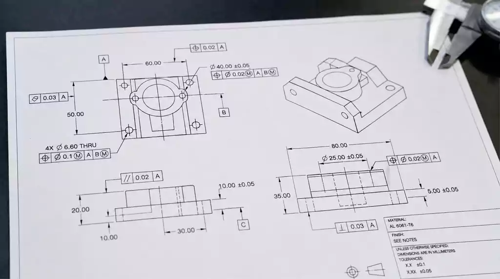
How Are Tolerances Specified on Technical Drawings?
Poorly defined drawings often create quoting confusion, inspection disputes, and expensive rework during CNC production.
Manufacturing tolerances are specified on engineering drawings using plus/minus dimensions, limit dimensions, GD&T symbols, fit callouts, and international standards to clearly define acceptable part variation during machining and inspection.
Common Ways Engineers Define Tolerances
The most common methods include:
| Method | Example | Usage |
|---|---|---|
| Plus/Minus Tolerance | 50 ±0.02 mm | General dimensions |
| Limit Dimensioning | 49.98–50.02 mm | Precision fits |
| General Tolerance Notes | ISO 2768-m | Non-critical features |
| GD&T Symbols | Position, flatness | Functional geometry |
GD&T becomes very important when dimensional size alone cannot fully define how a part should function.
For example, two holes may both measure correctly, but their relative position could still cause assembly failure. That is where positional tolerance helps.
Common Drawing Problems I See
Many RFQs contain these issues:
- Missing datum references
- Over-constrained dimensions
- Inconsistent tolerance units
- Impossible geometric requirements
- No distinction between critical and non-critical features
I always recommend identifying critical-to-function dimensions clearly. This helps the machinist focus inspection effort where it matters most.
General Tolerance Standards
Many manufacturers use general tolerance systems for non-critical dimensions.
A common example is ISO 2768.
| ISO 2768 Grade | Typical Use |
|---|---|
| Fine (f) | Precision components |
| Medium (m) | Standard machined parts |
| Coarse (c) | Welded or fabricated parts |
| Very Coarse (v) | Large rough structures |
Using standard tolerance notes simplifies drawings and reduces unnecessary dimension clutter.3
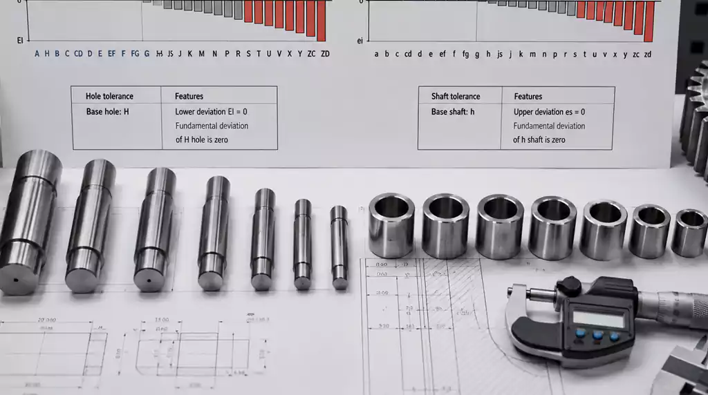
Understanding Fits and ISO Tolerance Systems
Many assembly failures happen because engineers select the wrong fit type instead of the wrong dimension.
Fits and ISO tolerance systems define the relationship between mating holes and shafts. Proper fit selection controls clearance, interference, assembly force, rotational movement, and long-term mechanical stability in CNC-machined assemblies.
The Three Main Fit Categories
| Fit Type | Description | Typical Application |
|---|---|---|
| Clearance Fit | Space exists between parts | Sliding assemblies |
| Transition Fit | Small clearance or interference | Accurate positioning |
| Interference Fit | Parts press together tightly | Permanent assemblies |
For example, a sliding linear shaft often uses a clearance fit, while a bearing press fit uses interference.
Understanding ISO Hole and Shaft Systems
The ISO system uses letters and numbers to define tolerance zones.
Examples include:
- H7
- g6
- h6
- p6
In simple terms:
- Uppercase letters describe holes
- Lowercase letters describe shafts
- Numbers define tolerance grade accuracy
A common CNC assembly combination is H7/h6. It gives controlled clearance for rotating parts.
Many engineers use detailed tolerance and fit guides during part design because selecting the correct fit often has a bigger impact on assembly performance than tightening dimensional tolerance alone.
Why Proper Fit Selection Matters
I once saw a customer use an interference fit for an aluminum gearbox housing without considering thermal expansion. After several hours of operation, the bearing preload became excessive and caused overheating.
We redesigned the fit using a controlled transition fit. The gearbox temperature dropped immediately during testing.
This is why fit design should always consider:
- Material expansion
- Operating temperature
- Load direction
- Lubrication
- Assembly method
- Maintenance requirements
Tolerance design is not only about dimensions. It is about how real mechanical systems behave during operation.
Common Tolerance Symbols, Charts, and International Standards
Global manufacturing projects often fail when suppliers and buyers use different tolerance systems or drawing conventions.
Tolerance symbols and international standards create a unified engineering language for CNC machining, helping engineers, suppliers, and inspectors communicate dimensional requirements clearly across global manufacturing projects.
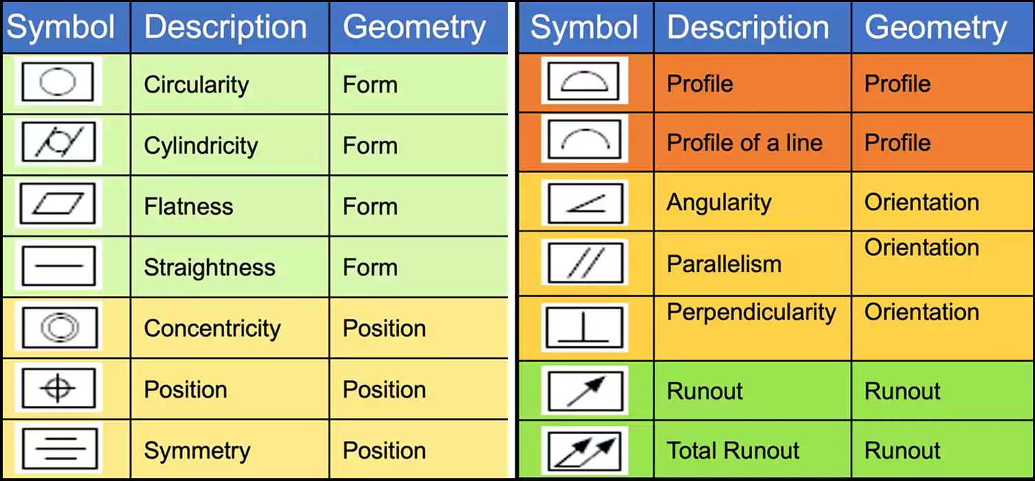
Common GD&T Symbols
| Symbol | Meaning |
|---|---|
| Flatness | Surface uniformity |
| Parallelism | Parallel relationship |
| Perpendicularity | 90° orientation |
| Concentricity | Shared center axis |
| Position | Feature location accuracy |
| Circularity | Roundness control |
| Runout | Rotational accuracy |
GD&T symbols help define functional requirements more clearly than dimensions alone.
Major International Tolerance Standards
| Standard | Region | Purpose |
|---|---|---|
| ISO 2768 | International | General tolerances |
| ISO 286 | International | Fits and tolerances |
| ASME Y14.5 | USA | GD&T standard |
| DIN Standards | Germany | Mechanical engineering |
| JIS Standards | Japan | Industrial manufacturing |
In global CNC sourcing, I often see customers combine ISO and ASME standards within the same drawing package. That can create confusion if definitions are inconsistent.
How I Recommend Managing Tolerances
After years in CNC machining, I now follow several simple rules:
- Tighten tolerances only on critical features
- Use standard fits whenever possible
- Apply GD&T for functional geometry
- Match tolerance level to process capability
- Discuss manufacturability early with suppliers
The best machining projects happen when design engineers and machinists work together from the beginning instead of treating tolerance as only a drawing requirement.
Conclusion
Tolerance design is not about making every dimension as tight as possible. It is about creating parts that function reliably, assemble consistently, and remain cost-effective in real production. When engineers balance tolerance, fit, material behavior, and machining capability together, CNC manufacturing becomes faster, more stable, and far more predictable over the long term.

-
"Investment Casting Tolerances, https://alliedcasting.com/capabilities/investment-casting/general-casting-tolerances/. A technical reference on investment casting tolerances documents the typical dimensional variation achievable by the process, supporting the stated range for investment-cast parts. Evidence role: statistic; source type: institution. Supports: Investment casting typically achieves dimensional tolerances of about ±0.2 mm to ±0.5 mm.. Scope note: Tolerance capability varies with alloy, part size, geometry, foundry controls, and applicable standards; the cited range should be treated as a typical guideline rather than a universal guarantee. ↩
-
"ISO Limits and Fits Table", https://simplybearings.co.uk/shop/Info-Pages-ISO-Limits/c4746_4779/index.html?srsltid=AfmBOoo_hctlwg9HFFRsOQYhj-bf4L6QFGfYua1sEYVo1tSCxH151G3m. ISO system-of-limits references describe H7 as a standard hole-basis tolerance class commonly used in engineering fits, including locating fits where controlled clearance or transition behavior is required. Evidence role: definition; source type: institution. Supports: A bearing bore may require an H7 tolerance in applications where a controlled fit is needed.. Scope note: The source can support what H7 means and why it is used for fits, but the correct bearing-seat tolerance still depends on bearing type, load, speed, housing material, and service conditions. ↩
-
"ISO 2768-1:1989(en), General tolerances — Part 1", https://www.iso.org/obp/ui/en/#!iso:std:7748:en. ISO 2768 is a general tolerance standard for linear and angular dimensions without individual tolerance indications, which supports the use of standard tolerance notes to avoid specifying separate tolerances on every non-critical dimension. Evidence role: general_support; source type: institution. Supports: Standard tolerance notes can simplify drawings and reduce unnecessary dimension clutter.. Scope note: The source supports the drafting rationale by context; it may not provide empirical evidence that drawings are always simpler or less cluttered in practice. ↩
