Choosing the wrong gear manufacturing method can lead to noise, early failure, or cost overruns that only appear after assembly.
Gear manufacturing methods define gear accuracy, strength, surface finish, and cost. The right process depends on gear type, tolerances, batch size, and load conditions. Understanding these factors helps engineers and buyers avoid risk and select reliable manufacturing partners.
I see many projects delayed because gear process decisions are made too late. Engineers focus on geometry, while buyers focus on price. Both matter. I want to explain how gear manufacturing choices connect design intent with production reality, and why this choice should happen early.
Why Does Gear Manufacturing Method Selection Matter?
A gear that looks perfect on a drawing can still fail if it is made with the wrong process.
The manufacturing method determines achievable accuracy, tooth strength, surface finish, and repeatability. It also affects delivery time and cost stability, especially for custom and non-standard gears.
In my early years on the shop floor, I often saw gears rejected after assembly testing. The design was fine. The material was correct. The problem was process mismatch1. A milling process was used where hobbing was needed, or grinding was skipped to save cost. These decisions look small at quoting stage but become very expensive later.
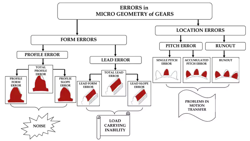
Accuracy, load, and noise are linked
Gear accuracy grades under ISO2 or AGMA standards3 directly affect load distribution and noise. Some processes can only reach certain grades.
Process choice affects scalability
A method that works for prototypes may fail for production volumes. Tooling wear, cycle time, and repeatability must be considered early.
| Factor | Poor Process Choice | Correct Process Choice |
|---|---|---|
| Accuracy | Inconsistent tooth form | Stable, repeatable quality |
| Cost | Hidden rework costs | Predictable unit cost |
| Delivery | Delays from scrap | Stable lead times |
What Gear Types Are Commonly Used in Industrial Applications?
Not all gears behave the same, and not all processes suit every gear type.
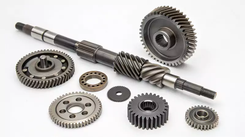
Industrial gear applications mainly use spur, helical, bevel, worm, and fully customized gears. Each type has different load behavior and manufacturing limits.
I usually ask customers first how the gear will be used, not how it looks. Application defines gear type, and gear type narrows down manufacturing options.
Spur gears
Simple geometry. Easy inspection. Sensitive to noise at high speed.
Helical gears4
Better load sharing. Quieter operation. More complex cutting and inspection.
Bevel gears
Used for intersecting shafts. Alignment and tooth accuracy are critical.
Worm gears5
High reduction ratios. Sliding contact increases heat and wear demands.
Custom and non-standard gears
Often combine features, materials, or space constraints. These always require early process discussion.
What Are the Main Gear Manufacturing Methods?
Each gear manufacturing method has clear strengths and limits.
The most common industrial methods include hobbing, shaping, CNC milling, broaching, and grinding. Selection depends on gear geometry, volume, accuracy grade, and cost targets.

I rely on a small number of proven processes rather than chasing novelty. Control matters more than variety.
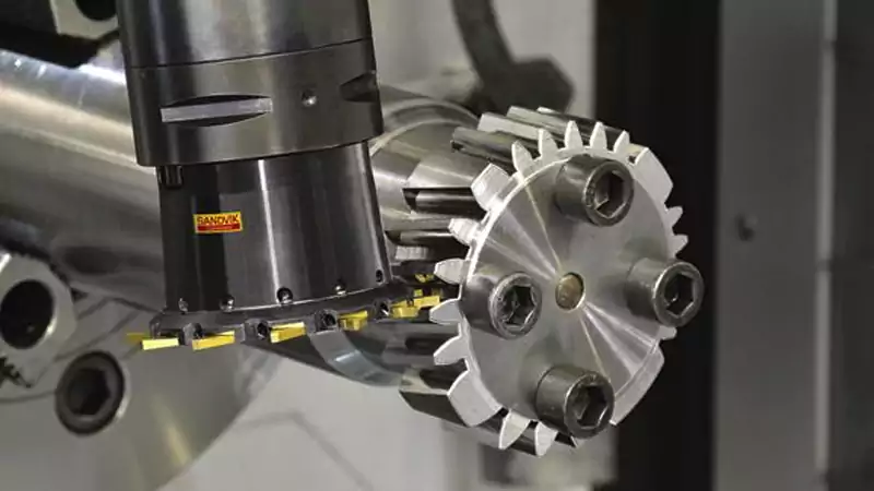
Gear hobbing
Hobbing is fast and stable for external gears. It suits medium to large batches. Accuracy is good, but tool access is limited for internal gears.
Gear shaping
Shaping works well for internal gears and complex profiles. Cycle time is longer, but flexibility is high.
CNC gear milling
This is ideal for prototypes and non-standard gears. It allows fast iteration but is slower and less consistent for large volumes.
Gear broaching
Broaching is efficient for internal gears in large volumes. Tooling cost is high, so it only makes sense for mass production.
Gear grinding
Grinding improves accuracy and surface finish after heat treatment. It is essential for high-speed or low-noise applications.
| Method | Accuracy Potential | Volume | Typical Use |
|---|---|---|---|
| Hobbing | Medium–High | Medium–High | External gears |
| Shaping | Medium | Low–Medium | Internal gears |
| CNC Milling | Medium | Low | Custom gears |
| Broaching | Medium | Very High | Internal mass production |
| Grinding | Very High | Medium | Precision finishing |
How Are Spur Gears Manufactured in Practice?
Spur gears look simple, but the process choice changes results.
Spur gears are commonly made by hobbing or CNC milling, then heat treated and sometimes ground. The right path depends on tolerance, noise limits, and batch size.
I often see spur gears underestimated. Many failures start here.
Hobbing versus CNC milling
Hobbing gives better tooth consistency for production. CNC milling is better for complex hubs or low quantities.
Heat treatment impact
Distortion after heat treatment can destroy accuracy. Grinding may be required if tolerances are tight.
Small batch versus production
One-off gears should avoid expensive tooling. Production gears must protect cycle time and tool life.
| Requirement | Best Option |
|---|---|
| Prototype | CNC milling |
| Medium batch | Hobbing |
| Low noise | Hobbing + grinding |
| Tight tolerance | Grinding after heat treat |
What Accuracy Standards and Quality Controls Matter Most?
Accuracy claims mean nothing without standards and inspection.
ISO and AGMA gear accuracy grades define allowable tooth errors. Quality systems, traceability, and inspection methods ensure gears meet those grades consistently.
When working with EU clients, documentation often matters as much as the part itself.
ISO and AGMA grades
Lower numbers mean higher accuracy. Not every process can achieve low-grade numbers reliably.
Inspection systems
Gear measuring machines, CMMs, and roll testing confirm real performance, not just dimensions.
Traceability
Batch records, heat treatment charts, and inspection reports reduce risk for long-term programs.
How Do I Choose the Right Gear Manufacturing Method?
Most wrong choices come from missing early questions.
The best gear process balances volume, tolerance, load, lead time, and cost. Early discussion between design, purchasing, and manufacturing prevents expensive changes later.
I use a simple logic when reviewing new projects.
Volume first
Volume defines tooling logic. Low volume favors flexible CNC methods.
Load and speed second
Higher load or speed pushes toward better accuracy and finishing processes.
Cost over lifecycle
Cheapest unit price can cause higher ownership cost due to noise, wear, or scrap.
| Decision Factor | Key Question |
|---|---|
| Volume | One-off or repeat order? |
| Accuracy | ISO 8 or ISO 6? |
| Load | Static or dynamic load? |
| Timing | Prototype or long-term supply? |
What Is Possible for Custom and Non-Standard Gear Manufacturing?
Non-standard gears are where trust is earned.
Custom gear manufacturing requires design-for-manufacturing support, flexible processes, and clear communication on limits, tolerances, and risks.
I enjoy these projects most. They require experience more than machines.
DFM support
Minor design changes can simplify production without changing function.
Material selection
Material choice affects wear, noise, and heat treatment distortion.
Prototype to production transition
Processes must scale without redesign.
Case Study: Custom Helical Gear for Automation System
| Parameter | Value |
|---|---|
| Gear Type | Helical |
| Module | 2.5 |
| Teeth | 34 |
| Material | 42CrMo4 |
| Heat Treatment | Q&T to 28–32 HRC |
| Accuracy Target | ISO 7 |
| Batch Size | 120 pcs |
| Process | CNC milling → Hobbing → Heat treat → Grinding |
The customer needed low noise and fast delivery. We adjusted tooth modification before grinding. The final noise level dropped by 18%, and scrap rate stayed below 1%.
Conclusion
The right gear manufacturing method aligns design intent, production reality, and long-term reliability. Early process decisions reduce risk, cost, and delays for both engineers and buyers.
-
Understanding process mismatch can help prevent costly errors in production and improve overall efficiency. ↩
-
Understanding ISO standards is crucial for ensuring gear accuracy and performance in various applications. ↩
-
Exploring AGMA standards will provide insights into gear design and manufacturing quality, enhancing your knowledge in the field. ↩
-
Explore this link to understand why helical gears are preferred for quieter and more efficient operation. ↩
-
Discover the pros and cons of worm gears to make informed decisions for your mechanical designs. ↩
