I often see shaft designs fail in testing. Most problems start in the drawing, not in the machine shop.
To design a reliable CNC-machined shaft, I define function first, set clear tolerances and fits, design for easy machining, choose the right material and heat treatment, and avoid common drawing mistakes that raise cost or risk.
If you are evaluating manufacturing partners or comparing technical capabilities, you can also explore our full range of precision CNC shaft solutions to see how different shaft types are produced and controlled.
A shaft looks simple in CAD. Real performance depends on load, speed, and manufacturing limits. I break the work into clear steps so the part works well and stays affordable. If someone is new to shaft applications, I often suggest starting with the basics of what a motor shaft is before moving into more complex designs.
How Do I Define Shaft Function and Core Engineering Requirements?
I have seen many shafts overdesigned in one area and weak in another. That happens when function is not clear from the start.
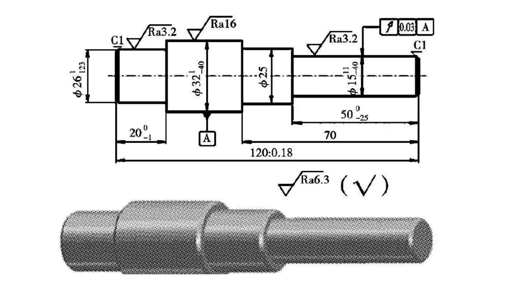
I begin shaft design by defining torque, speed, alignment, and load types. I then convert these needs into diameter, length, tolerances, surface finish, and runout limits that machining can realistically achieve.
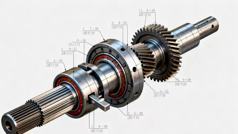
I first study what the shaft must do inside the machine. In many industrial systems, the role is similar to key elements described in transmission shafts, where power transfer, alignment, and fatigue life are critical.
Functional Breakdown
Torque Transmission
I check peak and continuous torque1. High torque raises shear stress. This often drives minimum diameter.
Rotational Speed Requirements
I review normal RPM and maximum RPM. High speed raises balance and critical speed concerns. Design rules used for a custom driveshaft also apply here when speed and vibration become critical.
Concentricity and Alignment
I look at how the shaft aligns with bearings, gears, or couplings. Poor alignment causes vibration and wear.
Bending, Axial, and Torsional Loads
I include belt pull, gear mesh forces, and thrust loads. These loads affect fatigue life.
Translating Function into Design Parameters
Once I understand loads, I move to geometry and tolerances. This step is a a core part of any solid custom shaft manufacturing guide, since design decisions directly affect machinability.
| Design Item | Why I Care | Typical Approach |
|---|---|---|
| Diameter & Length2 | Control strength and stiffness | Size from torque and deflection limits |
| Fits (H7/h6 etc.) | Ensure correct assembly | Match bearing and hub standards |
| Surface Finish | Affects wear and sealing | Ground or fine-turned for seats |
| Runout & Straightness | Control vibration | Tight limits for high-speed shafts |
| Critical Speed | Avoid resonance | Keep working speed well below |
I treat this step as the bridge between theory and real machining.
How Do I Design for Manufacturability and Cost Efficiency?
I have reduced shaft cost many times just by changing a few dimensions on a drawing. Small design choices make big differences in machining time.
I lower shaft cost by avoiding unnecessary tight tolerances, using standard tool sizes, simplifying features, and choosing where grinding is truly needed instead of defaulting to expensive processes.
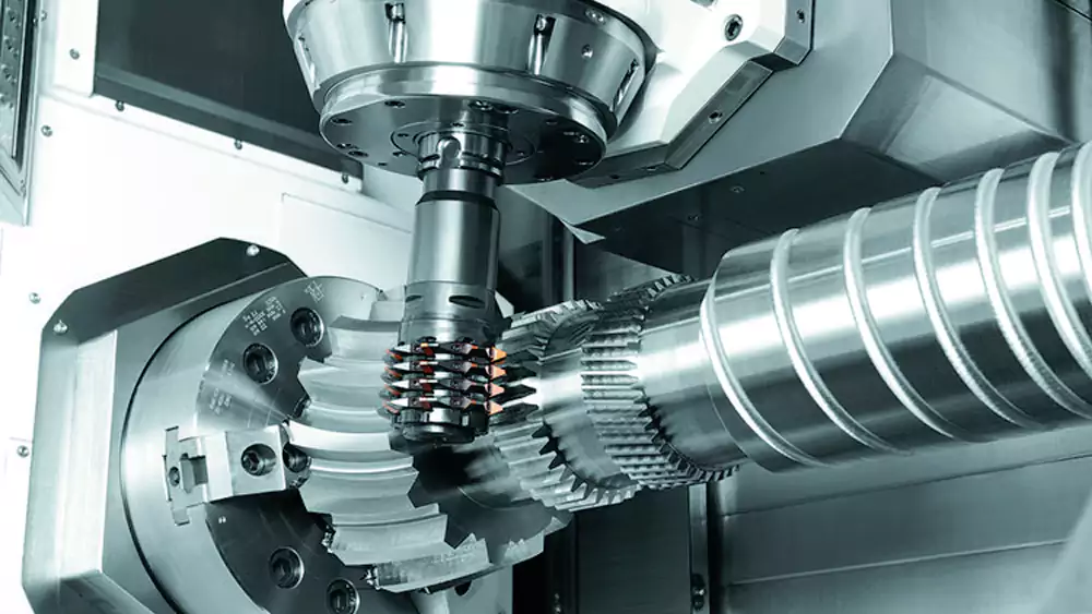
Many of these decisions come from experience in CNC machining of shafts, where setup count, tool reach, and tolerance strategy directly affect price.
Avoiding Unnecessary Tight Tolerances
I only tighten tolerances on functional surfaces. Over-tight tolerances increase machining time and inspection cost.
Using Standard Radii and Chamfers
I match corner radii to common tool sizes. Custom radii often require special tools or slow machining.
Reducing Setup Changes
I try to keep most features machinable in one or two setups. Extra setups increase runout risk and cost.
Turned vs Ground Surfaces
Grinding gives high accuracy and fine finish. It also costs more. I reserve grinding for bearing seats or seal areas when required.
Batch Size and Unit Cost
Process choice depends on volume.
| Batch Size | Preferred Process Focus | Cost Impact |
|---|---|---|
| Prototype | Flexible CNC turning | Higher unit cost |
| Small Batch | Optimized CNC process | Balanced |
| Large Batch | Process optimization, special tooling | Lower unit cost |
I always design with the expected production volume in mind.
How Do I Choose Materials and Heat Treatment for Reliability?
Material choice affects strength, wear life, and distortion. I have seen good designs fail because material or heat treatment was not planned well.
I select shaft materials based on torque, speed, and environment. I plan heat treatment early, since hardening improves strength but can cause distortion that must be controlled in design and machining.
Material selection is also a key factor in custom automotive shaft machining, where weight, fatigue life, and consistency are tightly controlled.
Common CNC Shaft Materials
| Material | Typical Use | Key Benefit |
|---|---|---|
| 1045 Steel | General machinery | Low cost, easy to machine |
| 4140 / 42CrMo43 | High load shafts | High strength after heat treat |
| Stainless Steel | Wet or corrosive areas | Corrosion resistance |
Matching Material to Application
High torque and shock loads push me toward alloy steels. Corrosive environments push me toward stainless grades.
Through Hardening vs Surface Hardening
Through hardening raises core strength. Surface hardening improves wear resistance on journals. I choose based on stress depth.
Case Study from My Experience
I once helped redesign a gearbox output shaft.
| Parameter | Value |
|---|---|
| Material | 42CrMo4 |
| Heat Treatment | Quenched & tempered, 30–34 HRC |
| Shaft Length | 460 mm |
| Bearing Seat Tolerance | h6 |
| Max Torque | 950 Nm |
| Max Speed | 3,000 RPM |
| Runout Limit | 0.02 mm |
The first version warped after heat treatment. I added extra grinding allowance and improved support during quench. The final shafts met runout limits and field life doubled.
Planning for Distortion and Fatigue
I add machining allowance for post-heat-treatment grinding. I avoid sharp transitions to reduce stress concentration and improve fatigue life.
What Common Shaft Design Mistakes Should I Avoid and How Do I Work Better with Machining Suppliers?
I have made some of these mistakes early in my career. I learned that small drawing issues can cause big shop-floor problems.
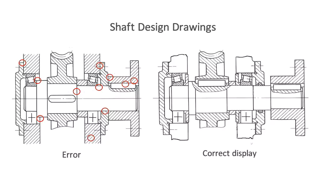
Common shaft design errors include over-tight tolerances, poor bearing seat design, sharp shoulders, ignoring tool access, and forgetting heat-treatment distortion. Clear drawings and application data help suppliers quote and machine parts correctly.
Working with suppliers who provide full precision CNC shaft solutions also reduces risk, since they understand both design intent and machining limits.
Five Common Shaft Design Mistakes
-
Over-Specified Tolerances
I now tighten tolerances only where function demands it. -
Poor Bearing Seat Design
Wrong fits cause creep or assembly damage. -
Sharp Shoulders
I add proper fillet radii to reduce stress concentration. -
Ignoring Tool Access
Deep narrow grooves can be hard or costly to machine. -
Ignoring Heat Treatment Distortion4
I always leave stock for finish grinding if needed.
Preparing a Supplier-Friendly Shaft Drawing
| Information | Why It Helps |
|---|---|
| Marked Functional Surfaces | Supplier focuses on key areas |
| Clear Tolerances | Reduces back-and-forth questions |
| Surface Finish Notes | Ensures correct process choice |
| Heat Treatment Specs | Prevents material mistakes |
| Annual Volume | Helps process planning and pricing |
When I share complete and clear data, suppliers respond faster and with more accurate quotes.
Conclusion
Good shaft design starts with function, respects machining limits, uses the right material, and avoids common drawing mistakes through clear communication.

-
Explore this link to understand how peak and continuous torque influence shear stress and minimum diameter in shaft design for better durability. ↩
-
Explore this link to understand how Diameter & Length control strength and stiffness, crucial for designing durable custom shafts. ↩
-
Explore this link to understand why 42CrMo4 is preferred for high load shafts and how its heat treatment enhances strength. ↩
-
Learning about heat treatment distortion is crucial to prevent dimensional errors and ensure quality in shaft production. ↩
