Many designs fail during machining because they look good in CAD but break real manufacturing rules.
Design for Manufacturing (DFM) helps engineers create parts that are easier, cheaper, and more reliable to produce by aligning design choices with real machining limits.
I have worked with thousands of drawings in my career as a machinist. I learned that simple and thoughtful designs always produce smoother machining, stable quality, and shorter lead times. When engineers and procurement teams understand DFM, projects become predictable and suppliers become easier to manage.
What is Design for Manufacturing (DFM)?
Many teams run into delays because they finalize a design before checking how it behaves in real production.
DFM means designing a part so it matches the capabilities of the chosen manufacturing process, preventing cost spikes, delays, and quality problems.
A deeper look at what DFM really solves
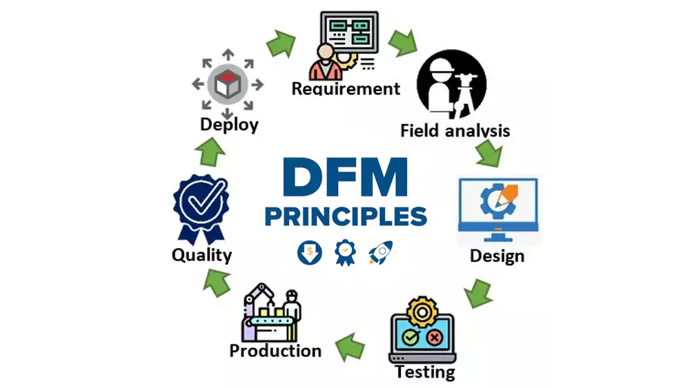
I see DFM as a set of rules that connect design decisions1 with machining behavior. When engineers understand how a tool cuts, how material reacts, or how fixtures hold a part, they avoid creating shapes that are slow, unstable, or impossible to produce. Procurement teams also benefit because DFM reduces rework, re-quotes, and quality disputes. A good DFM mindset prevents problems before they happen.
DFM vs DFA: What Are the Differences and Why Both Matter?
I often see engineers mix up DFM and DFA, and that usually causes confusion during production planning.
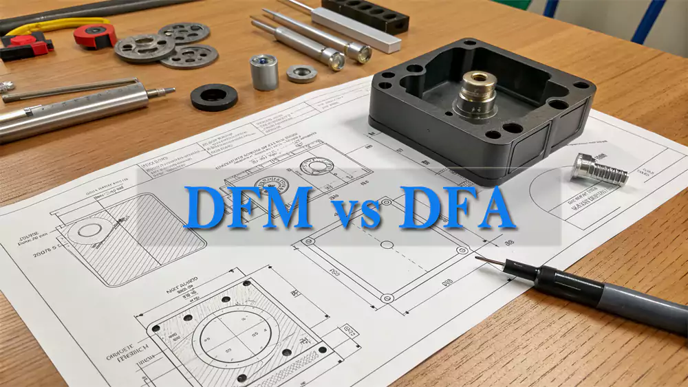
DFM focuses on designing parts that can be made efficiently, while DFA focuses on designing parts that can be assembled smoothly.
How each one affects real manufacturing
DFM prevents hard-to-machine shapes, risky tolerances, or thin walls. DFA2 prevents difficult assembly steps, misalignment, and high labor time. In my shop, I have seen simple changes—like adding chamfers, adjusting hole positions, or improving alignment surfaces—reduce both machining time and assembly mistakes. When both principles work together, the supply chain becomes more stable from machining to final assembly.
Why DFM Matters for CNC Machining, Injection Molding, and Sheet Metal?
Choosing a process first and checking manufacturability later often leads to redesigns, overruns, and unpredictable costs.
DFM ensures your design fits the limits of CNC machining, injection molding, or sheet metal forming so the part can be produced without trouble.
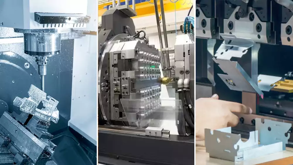
Process-specific rules every engineer should know
CNC Machining
- Tools have minimum corner radii
- Thin walls cause vibration
- Deep pockets require special strategies
- Tight tolerances slow down machining
Injection Molding
- Draft angles are required
- Uniform wall thickness prevents warping
- Ribs improve stiffness without adding weight
Sheet Metal
- Bend radii must match material rules
- Hole distances must avoid deformation
- Sharp corners weaken the part
When the design matches the process, both cost and quality become stable. I always tell customers to check manufacturability before freezing a drawing.
Key DFM Rules Every Engineer Should Know?
Most machining problems come from designs that ignore a few basic manufacturability rules.
The key DFM rules include proper wall thickness, realistic tolerances, internal radii, standard threads, and simplified geometry.
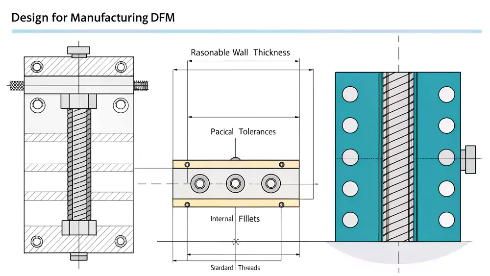
The core rules I use in real machining
1. Wall Thickness
Thin walls cause chatter and distortion.
- Metals: ≥ 1.0 mm
- Plastics: ≥ 1.2 mm
2. Internal Radii
Sharp corners require tiny tools that break easily.
Use radii larger than the tool radius—ideally 1.5× the tool.
3. Tolerances
Unnecessary ±0.01 mm tolerances multiply cost.
Use tight tolerances only when function demands it.
4. Threads
Use standard depths and sizes.
Deep threads slow production and increase tap breakage.
5. Geometry
Every extra surface, cavity, or decorative feature adds machine time.
Simple designs always machine better.
These rules come from years of running everything from 3-axis mills to 5-axis machines.
How DFM Reduces Cost and Lead Time?
I have seen cost reductions happen before a part even reaches the machine—because cost begins at the design stage.
DFM reduces cost by lowering setup times, shortening toolpaths, reducing scrap risk, and removing unnecessary complexity.
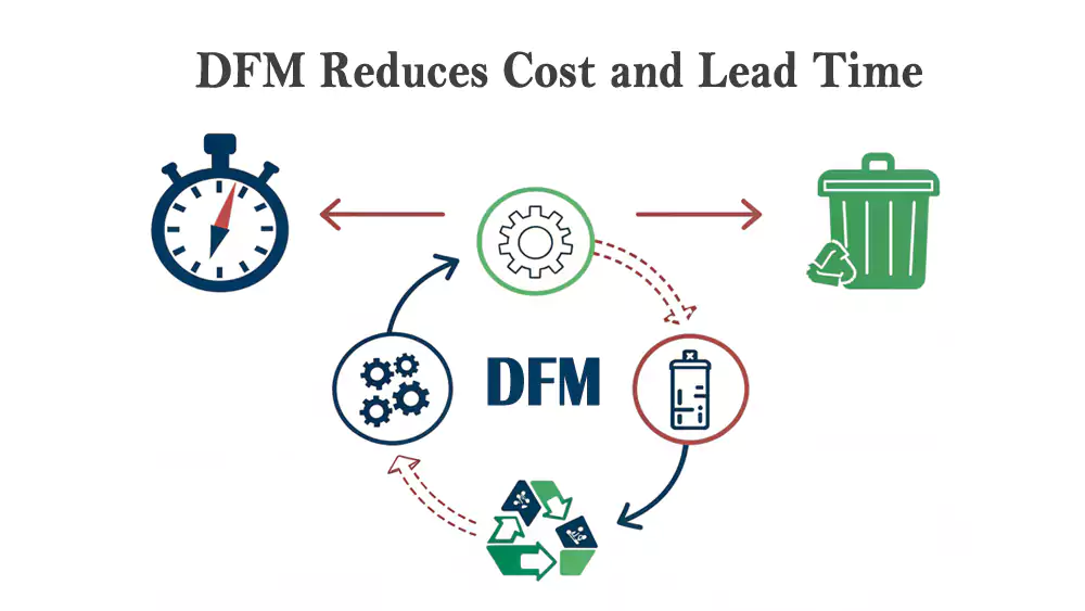
How cost drops when DFM is applied
Fewer setups
Simplified geometry avoids extra clamping and rotations.
Faster toolpaths
Larger radii and standard features let tools move faster and last longer.
Lower inspection time
Realistic tolerances reduce CMM checks3 and manual measurements.
Fewer mistakes
DFM prevents scrap caused by thin walls, poor heat distribution, or tool deflection.
For procurement teams, these improvements lead to stable prices and predictable timelines.
Common DFM Mistakes Engineers Should Avoid
I have seen certain design mistakes repeat across industries—from automation to medical devices.
Common mistakes include thin walls, tight tolerances without reason, deep narrow holes, tiny radii, and non-standard features.
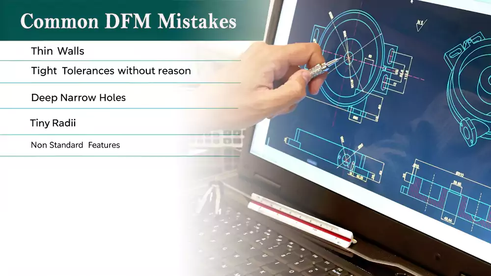
Mistakes that almost always cause trouble
Thin Walls
They vibrate, warp, and change dimension under heat.
Very Tight Tolerances
They slow machining and inspections. Only apply them to critical areas.
Deep Small-Diameter Holes
These require specialized tools, peck drilling, and more time.
Sharp Internal Corners
No end mill can create a perfectly sharp inside corner. Radii are required.
Unnecessary Surface Aesthetics
Polished surfaces or decorative edges increase cost but do not improve function.
Avoiding these mistakes protects both time and budget.
A Practical DFM Case Study (Europe Client Example)?
Theory is helpful, but real numbers explain DFM better than anything.
A European automation company reduced machining cost by 28% and cut lead time by 5 days after applying basic DFM adjustments.
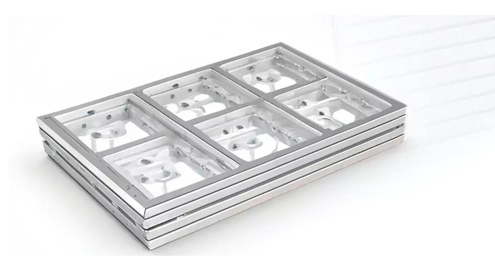
Case Details
A customer asked me to machine 500 aluminum brackets. Their original design had deep pockets, thin walls, and unnecessary ±0.01 mm tolerances. I suggested several improvements. They accepted, and the results were immediate.
| Attribute | Before DFM | After DFM |
|---|---|---|
| Material | 6061 | 6061 |
| Critical Tolerance | ±0.01 mm everywhere | ±0.03 mm except on functional areas |
| Wall Thickness | 0.6 mm | 1.2 mm |
| Internal Corners | Sharp | R2 |
| Cycle Time4 | 14.8 min | 10.1 min |
| Lead Time | 12 days | 7 days |
| Cost Reduction | — | 28% |
The part function stayed the same, but the project became cheaper, faster, and more stable. This is the true value of DFM in real manufacturing.
How to Work with a Supplier to Apply DFM Correctly?
The best results happen when designers and machinists work together early.
DFM works best when engineers share clear drawings, explain real functional needs, and allow suppliers to offer machining-based suggestions.
Practical steps that always improve outcomes
Provide Clear Drawings
Use simple tolerance callouts and leave room for machining strategies.
Tell the supplier which surfaces matter most.
This helps us decide where to apply tight tolerances.
Ask for Early DFM Feedback
A quick review often prevents expensive redesigns.
Approve Changes Quickly
Fast communication helps suppliers keep production moving.
Good cooperation reduces cost and protects the project from delays.
Conclusion
DFM is not about compromising your design. It aligns design with real manufacturing rules so parts become easier, faster, and more affordable to produce.

-
Exploring this topic can provide insights into optimizing designs for better manufacturability and cost-effectiveness. ↩
-
This resource will help you understand how DFA streamlines assembly processes and minimizes errors. ↩
-
View more information about coordinate measuring machines. ↩
-
Exploring cycle time reduction techniques can lead to increased efficiency and faster production rates in your operations. ↩
