Last updated: October 13, 2026
This article has recently been thoroughly revised to ensure we provide you with the most accurate guide to CNC machining.
Poorly machined surfaces can cause assembly problems, uneven contact, and costly rework. Precision face milling helps control surface quality and dimensional accuracy before these problems reach the production line.
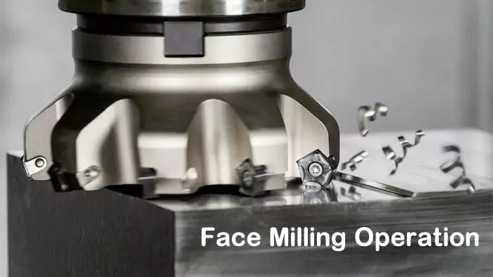
Face milling is a CNC machining process that removes material from a workpiece to create a flat surface. A rotating cutter uses cutting edges on its face and periphery to produce the required surface dimensions, flatness, and finish. This process is widely used for mounting faces, reference surfaces, and other features that require reliable dimensional accuracy.
A good face-milled surface depends on more than the cutting tool. Workholding, cutter geometry, toolpath planning, and cutting parameters all affect the final result. A surface may look smooth but still fail to meet the required flatness or assembly tolerance. These details matter when manufacturing custom CNC parts because even small errors can affect downstream machining and final assembly. Understanding how face milling works, which tools and parameters affect quality, and when to use it can help engineers and purchasing managers make better manufacturing decisions.
What Is Face Milling and How Does It Work?
Poor planning can create uneven surfaces, vibration marks, and dimensional errors. These problems can affect later operations and increase production costs.
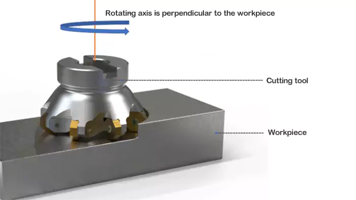
Face milling works by rotating a multi-edge cutting tool across a workpiece to remove material and produce a flat surface. The process can control surface dimensions, flatness, and finish when the cutter, workholding, and cutting parameters are properly selected.
How to Plan a Face Milling Operation
The first step is to review the engineering drawing and identify the required surface dimensions, flatness, parallelism, surface roughness, and relationship to other features. These requirements determine how much material to remove and whether the operation needs a roughing pass followed by a finishing pass.
Next, the workpiece must be secured on the machine table or in a suitable fixture. The part needs enough support to resist cutting forces without shifting or bending. Thin plates and irregular castings require special attention because excessive clamping force can distort the part before machining begins.
Tool selection and toolpath planning come next. The cutter diameter, insert geometry, spindle speed, feed rate, and depth of cut must work together. The available machining allowance also needs to be checked. If the raw surface contains excessive stock or casting defects, a single finishing pass may not be enough.
The Main Steps in Face Milling
- Inspect the raw part: Check the material, dimensions, surface condition, and available machining allowance.
- Secure the workpiece: Choose a fixture that provides stable support and repeatable positioning.
- Select the cutter: Match the cutter body and inserts to the material, surface size, and required finish.
- Set cutting parameters: Calculate spindle speed and feed rate based on the cutter diameter, number of teeth, and material.1
- Machine the surface: Use roughing passes when necessary, followed by a controlled finishing pass.
- Inspect the result: Measure the relevant dimensions and check flatness, surface finish, and any drawing-specific requirements.
The first reference surface deserves particular attention. Later operations may use it to locate the part, so an error at this stage can carry through the entire machining process.
What Tools and Parameters Affect Face Milling Quality?
A cutter that works well on one material may perform poorly on another. Incorrect inserts or cutting parameters can cause chatter, built-up edges, rapid tool wear, and inconsistent surface quality.
Face milling quality depends on cutter diameter, insert geometry, tool condition, spindle speed, feed rate, depth of cut, tool engagement, workholding, and machine rigidity. Matching these factors to the workpiece material and drawing requirements helps achieve consistent surface finish and dimensional accuracy.
Choosing the Right Face Milling Cutter
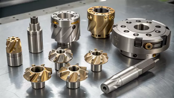
Three common cutter types are worth considering when planning a face milling operation.
| Cutter type | Typical use | Main consideration |
|---|---|---|
| Indexable face mill | Flat surfaces on aluminum, steel, and cast iron | Insert geometry, cutter diameter, and cutting stability |
| High-feed face mill | High material removal rates with relatively shallow cutting depths | Machine capability, insert design, and toolpath strategy |
| Solid carbide face milling cutter | Smaller features and selected precision applications | Tool diameter, rigidity, material, and cost |
For many custom metal parts, an indexable face mill is a practical choice because individual inserts can be replaced without changing the entire cutter. However, the insert grade and geometry must suit the material. Aluminum often benefits from sharp cutting edges that reduce material buildup, while steel and cast iron may require different edge preparations and wear-resistant grades.
How to Set Cutting Parameters
Spindle speed is calculated using the cutting speed recommended for the selected tool and material. The basic formula is:
[
n=\frac{1000V_c}{\pi D}
]
Here, (n) is spindle speed in revolutions per minute, (V_c) is cutting speed in meters per minute, and (D) is cutter diameter in millimeters.
For a face mill with multiple cutting edges, the feed rate can be calculated using:
[
V_f=n \times z \times f_z
]
Here, (V_f) is feed rate in millimeters per minute, (z) is the number of effective cutting teeth, and (f_z) is feed per tooth in millimeters.
These formulas provide a starting point rather than a guaranteed production setting. Machine power, tool overhang, workpiece rigidity, insert recommendations, and actual cutting behavior must also be considered.
Practical Case Study: Face Milling an Aluminum Mounting Plate
The following example illustrates how a face milling operation might be planned for a custom aluminum mounting plate. The values are illustrative starting parameters, not verified production records or universal recommendations.
| Item | Example specification |
|---|---|
| Workpiece material | Aluminum alloy 6061-T6 |
| Cutter type | Indexable face mill |
| Cutter diameter | 50 mm |
| Number of effective teeth | 5 |
| Cutting speed | 300 m/min |
| Calculated spindle speed | Approximately 1,910 rpm |
| Feed per tooth | 0.08 mm/tooth |
| Calculated feed rate | Approximately 764 mm/min |
| Roughing depth of cut | 1.0 mm |
| Finishing depth of cut | 0.2 mm |
| Initial radial engagement | 25 mm |
| Coolant strategy | Based on insert guidance and machine setup |
At a cutting speed of 300 m/min, a 50 mm cutter gives a calculated spindle speed of approximately 1,910 rpm. With five effective teeth and a feed per tooth of 0.08 mm, the calculated feed rate is about 764 mm/min.
Before using these settings, the machine, cutter, and workholding must be checked for compatibility. A test cut can then help verify the results. If chatter appears, fixture rigidity, cutter runout, tool overhang, and tool engagement should be checked before several parameters are changed at once.
Visible feed marks may indicate a need to review insert condition, feed rate, or cutter geometry. If the mounting face fails its flatness requirement, workpiece distortion and temperature effects also need to be investigated. A finishing pass cannot correct every problem caused by poor support or excessive residual stress.2
How to Control Surface Finish and Dimensional Accuracy
Cutter runout is an important factor because uneven insert heights can cause one insert to remove more material than the others. This can create visible marks and shorten tool life. Excessive tool overhang should also be avoided because it can increase vibration.
For tight-tolerance parts, the machined surface needs to be inspected against the engineering drawing. Suitable measuring equipment must be selected for the tolerance involved. A consistent machining sequence across production batches also helps prevent unexpected variation caused by changes in tool condition or setup.
What Is the Difference Between Face Milling and End Milling?
Choosing the wrong milling method can increase machining time, reduce tool access, and make it harder to achieve the required surface quality. The best choice depends on the geometry and function of each feature.
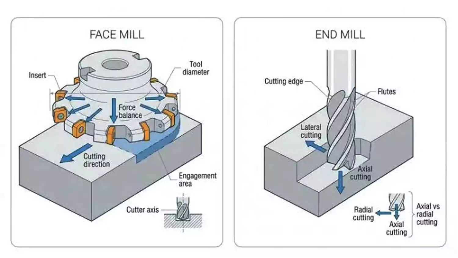
Face milling is mainly used to machine broad, flat surfaces with a cutter designed for that purpose. End milling uses the end and side cutting edges of an end mill to machine slots, pockets, shoulders, contours, and other detailed features. Both processes can be used on the same CNC component when its geometry requires different machining operations.
Main Differences Between the Two Processes
| Feature | Face milling | End milling |
|---|---|---|
| Main purpose | Producing flat faces and reference surfaces | Producing slots, pockets, contours, and shoulders |
| Typical cutter | Face mill with multiple inserts or cutting edges | Solid carbide or indexable end mill |
| Cutting edges | Often located on the face and outer circumference | Located on the end and along the sides |
| Typical application | Mounting faces, plate surfaces, and housing faces | Cavities, grooves, profiles, and narrow features |
| Productivity on broad surfaces | Often efficient with a suitable cutter and setup | Can be less efficient when covering large areas with a small tool |
| Access to narrow features | Limited by cutter diameter and geometry | Often better with a suitable small-diameter end mill |
When to Choose Face Milling
Face milling is a practical choice when a part needs a broad, flat surface and the cutter can cover the required area efficiently. Typical examples include mounting plates, machine brackets, housing interfaces, and flat reference surfaces on custom components.
A suitable face mill can remove material across a large area without requiring many narrow toolpath passes. This can reduce machining time and produce a consistent finish. The result still depends on cutter design, machine rigidity, tool engagement, and workpiece support.
The function of the machined face also matters. A mounting face may need to sit against another component without rocking or creating uneven contact. In that case, flatness and the relationship between the face and other datums may matter more than appearance alone.
When to Choose End Milling
End milling is more suitable when the geometry requires access to slots, pockets, internal corners, narrow channels, or curved profiles. An end mill can follow a programmed contour and remove material from areas that a large face mill cannot reach.
For example, a custom machine bracket may need a flat mounting surface, several bolt holes, and a recessed pocket. The main surface can be face milled first, followed by drilling or boring the holes and using an end mill to machine the pocket and profile.
The two processes are not always alternatives. Many CNC parts require both. Selecting the appropriate operation for each feature helps protect reference surfaces and reduce unnecessary repositioning.
When Should You Use Face Milling for Custom CNC Parts?
An unsuitable machining setup can cause scrap, rework, and delays. The part's geometry and functional requirements should be evaluated before deciding whether face milling is the best approach.
Face milling is suitable for mounting faces, reference surfaces, flat plates, machined casting faces, and housing interfaces when the surface dimensions and tolerances suit the cutter. Material, geometry, machining allowance, workholding, and inspection requirements should all be checked before selecting the process.
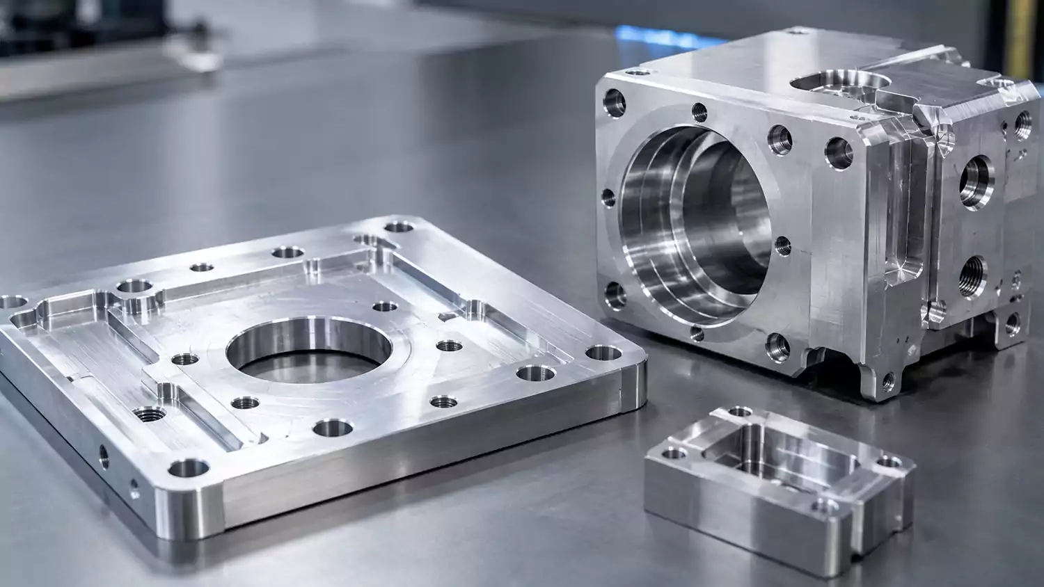
Common Applications in Custom CNC Manufacturing
Face milling is commonly used for several types of industrial components:
- Mounting plates and brackets: Flat surfaces help components sit correctly and maintain their intended position.
- Machine bases and support blocks: Reference faces support alignment during assembly and later machining operations.
- Gearbox and transmission housings: Selected exterior or mating faces may require machining after casting.
- Industrial automation components: Flat mounting surfaces help locate actuators, guides, sensors, and other equipment.
- Custom metal enclosures: Machined faces can provide controlled interfaces for covers, seals, and adjoining components.
The correct process depends on the actual drawing. A large flat surface may be suitable for face milling, while a narrow shoulder or deep pocket may need another tool. The raw part must also contain enough material to clean up the entire surface without reducing a wall or feature below its specified dimensions.
What to Check Before Quoting a Face Milling Job
A custom CNC machining request needs more than the overall part dimensions. The size of the surface to be machined, the material, the required flatness, the surface roughness, the datum scheme, and the available machining allowance all affect the process plan.
The starting condition of the part also matters. A workpiece may arrive as a billet, forging, casting, or previously machined component. Cast surfaces can contain uneven stock or defects that affect the machining plan. Face milling can remove surface material, but it cannot reliably repair deep porosity, internal cracks, or other defects that extend below the machining allowance.
Workholding is another major factor. Thin or irregular components may need dedicated fixtures or additional support. If the part distorts during clamping, the machined surface may become uneven after the fixture is released. This risk must be considered before committing to a tight flatness tolerance.
For production orders, tool life, cycle time, insert availability, inspection frequency, and batch consistency also affect the decision. A slightly faster cutting strategy may not be the best choice if it creates unstable dimensions or frequent tool changes. The goal is to achieve the required quality at a repeatable cost.
How Face Milling Affects Cost and Lead Time
Face milling can reduce cycle time when a suitable cutter removes material efficiently across a broad surface. It can also prevent downstream problems when the machined face serves as a reliable reference for later operations.
Cutting speed alone does not determine the best process. An aggressive setup may increase vibration, wear, and scrap risk. A stable setup with sensible cutting parameters may deliver a lower total manufacturing cost, even if the first pass takes slightly longer.
A reliable machining plan should clearly connect the drawing requirements with the proposed process. It should identify which surfaces will be face milled, how the part will be located, how critical dimensions will be inspected, and how consistent quality will be maintained across the batch.
For buyers sourcing custom CNC parts, a complete technical drawing should include material specifications, tolerances, surface finish requirements, quantities, and critical assembly features. These details help the manufacturer select the right cutter, estimate machining time, and identify risks before production begins. A supplier with established CNC machining capabilities can also evaluate how face milling fits into the wider manufacturing process, from initial machining to final inspection.
Conclusion
Face milling is more than a way to create flat surfaces. The right cutter, stable workholding, and controlled machining parameters help maintain dimensional accuracy, reduce rework, and improve assembly consistency. For custom CNC parts, these decisions should be based on the drawing, material, and functional requirements.
If you are developing a custom component, share your drawings and specifications with an experienced CNC machining team to evaluate the most suitable process for your project.
-
"Speeds and feeds", https://en.wikipedia.org/wiki/Speeds_and_feeds. Face milling cutting parameters such as spindle speed and feed per tooth are commonly determined from cutter diameter and tooth count using cutting-speed (S) and feed-rate relationships (e.g., V = πDN/1000 and material-dependent feed per tooth) found in machining handbooks and university machining references. Evidence role: general_support; source type: education. Supports: Calculate spindle speed and feed rate based on the cutter diameter, number of teeth, and material.. Scope note: Neutral sources can describe the standard calculation framework; the specific material-dependent constants and recommended ranges vary by tool geometry, insert grade, machine rigidity, and whether approach/finish passes are used. ↩
-
"Review Residual stress in metallic: Multi-scale formation ...", https://www.sciencedirect.com/science/article/pii/S258884042500112X. The source should explain how workpiece support stiffness and residual stresses can cause dimensional errors or distortion during machining, and that while finishing operations can improve surface/geometry locally, they may not fully eliminate errors stemming from deformation or stress relief. Evidence role: case_reference; source type: education. Supports: A finishing pass cannot always correct problems caused by poor support (stiffness) or excessive residual stress.. Scope note: May not be a direct guarantee/case for all parts; residual-stress effects are context-dependent and depend on material state and machining strategy. ↩
