Last updated on March 13, 2026, by Lucy
Many products fail not because the idea is bad, but because the design was never truly tested in the real world before production.
A functional prototype is a physical model built to perform the same mechanical and functional tasks as the final product. Engineers use it to validate performance, assembly, durability, and design logic before committing to expensive production tooling.

In my experience working with engineering teams, I have seen one simple truth. Drawings look perfect on a screen. Reality is very different. A functional prototype exposes the real behavior of a design. It shows problems early. That is why serious engineering teams rarely move to production without this step.
What Exactly Is a Functional Prototype in Product Development?
Many teams confuse appearance models with functional prototypes. This confusion often leads to incomplete testing and hidden design flaws.
A functional prototype is a working model that replicates the mechanical behavior, assembly structure, and performance of the final product. Its purpose is to verify engineering assumptions before mass production begins.

Functional Prototype vs Appearance Prototype
I often explain this difference to clients when they request prototypes. A cosmetic prototype focuses on visual design. A functional prototype focuses on engineering behavior.
| Prototype Type | Main Purpose | Typical Materials | Testing Focus |
|---|---|---|---|
| Appearance Prototype | Visual review | Resin, plastic, painted parts | Shape and aesthetics |
| Functional Prototype | Engineering validation | Aluminum, steel, engineering plastics | Strength, fit, motion |
| Engineering Prototype | System integration | Production materials | Full product testing |
A functional prototype must replicate several critical characteristics of the final product.
Parts must handle loads similar to real operating conditions. For example, brackets must support the same weight.
The prototype must assemble with other components exactly as the production version would. This often reveals tolerance issues.
Motion and Interaction
Moving parts must behave correctly. Hinges, sliders, and mounts must operate smoothly.
Durability
In some projects, engineers run thousands of cycles on a prototype to verify fatigue resistance.
In short, a functional prototype is not just a model. It is an engineering experiment.
Why Are Functional Prototypes Critical for Engineering Validation?
Skipping functional prototypes may save time early. But it usually creates expensive problems later.
Functional prototypes allow engineers to validate mechanical performance, assembly compatibility, and structural durability before investing in production tooling.

Design Validation
CAD models assume perfect conditions. Real materials behave differently. A functional prototype allows engineers to test real-world behavior.
I often see issues like:
- Unexpected deformation
- Stress concentration
- Heat expansion problems
- Fastener misalignment
These problems rarely appear in CAD simulations alone.
Assembly Testing2
Complex products often include dozens of parts. Even a 0.1 mm tolerance error can cause assembly failure.
Functional prototypes help engineers verify:
- Bolt alignment
- Component clearance
- Tool access during assembly
- Assembly sequence
This step can prevent major manufacturing delays.
Mechanical Performance Testing
Real testing conditions matter. Engineers may test:
- vibration resistance
- load bearing capacity
- wear and friction
- fatigue life
For example, vibration testing is critical in automotive and aerospace applications.
Risk Reduction Before Tooling
Injection molds or die casting tools can cost tens of thousands of dollars. Changing the design after tooling begins becomes extremely expensive.
Functional prototypes reduce this risk.
| Stage | Cost Impact |
|---|---|
| CAD modification | Low |
| Prototype revision | Moderate |
| Tooling modification | Extremely high |
From my experience in machining shops, one prototype revision can save months of redesign work.
How Are Functional Prototypes Manufactured? (CNC Machining vs 3D Printing)
Different prototype manufacturing methods serve different engineering needs.
Functional prototypes are commonly produced using CNC machining, metal 3D printing, polymer additive manufacturing, or vacuum casting depending on required strength, precision, and speed.

CNC Machining
CNC machining is the most common method for functional prototypes.
I recommend CNC machining when the prototype must closely match the final production material.
Typical materials include:
- Aluminum (6061, 7075)
- Stainless steel
- Brass
- Engineering plastics (POM, Nylon, ABS)
Advantages:
- High dimensional accuracy
- Excellent surface finish
- Real production materials
- Strong mechanical properties
Disadvantages:
- Higher cost for complex geometries
- Longer setup time
Metal 3D Printing
Metal additive manufacturing is useful for parts with complex internal structures.
Typical technologies include:
- SLM (Selective Laser Melting)
- DMLS (Direct Metal Laser Sintering)
Advantages:
- Complex internal channels3
- Lightweight lattice structures
- Reduced material waste
Limitations:
- Surface roughness
- Post-processing required
- Higher material cost
SLA and SLS Printing
Polymer 3D printing is ideal for fast iteration.
| Technology | Strength | Speed | Accuracy |
|---|---|---|---|
| SLA | Medium | Very fast | High |
| SLS | Good | Fast | Moderate |
These methods work well for rapid design verification.
Vacuum Casting
Vacuum casting is often used when engineers need small batch testing.
Benefits include:
- 10–50 parts quickly
- Consistent replication
- Lower cost than injection molding
However, material options are limited compared to machining.
How to Choose the Right Manufacturing Method for a Functional Prototype?
Many engineers struggle with prototype method selection. The wrong choice wastes time and money.
The best prototype manufacturing method depends on material requirements, mechanical strength, dimensional accuracy, production lead time, and cost constraints.
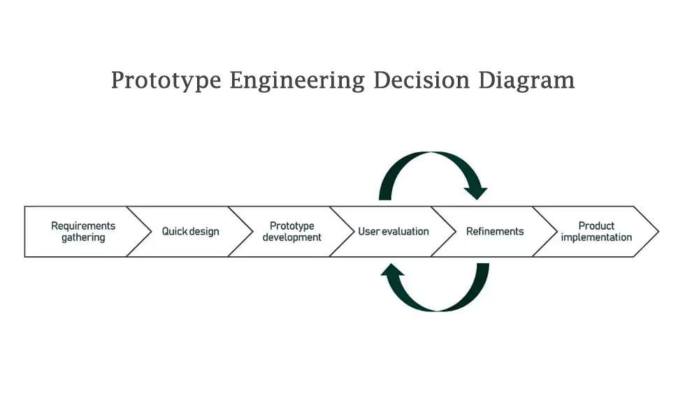
Engineering Decision Factors
When I help customers choose a process, I usually ask five questions first.
- What material must the part use?
- What loads will it experience?
- How tight are the tolerances?
- How fast is the deadline?
- How many parts are needed?
These answers guide the manufacturing decision.
Prototype Method Comparison
| Requirement | Recommended Method |
|---|---|
| High strength metal parts | CNC machining |
| Complex internal geometry | Metal 3D printing |
| Fast design iteration | SLA printing |
| Small batch testing | Vacuum casting |
Accuracy Considerations
Precision matters when parts interact with other components.
Typical tolerance capabilities:
| Process | Typical Tolerance |
|---|---|
| CNC Machining | ±0.01 mm |
| SLA Printing | ±0.05 mm |
| SLS Printing | ±0.10 mm |
| Metal 3D Printing | ±0.05–0.10 mm |
For high precision assemblies, CNC machining remains the preferred method.
In many real projects, engineers even combine multiple methods. For example, structural parts may be CNC machined while covers are SLA printed.
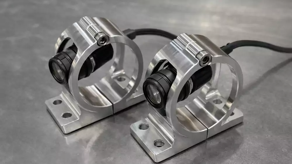
Case Study: Functional Prototype for an Automotive Sensor Mount
A few years ago I worked with an engineering team developing a sensor mounting bracket for an automotive monitoring system.
The team needed a functional prototype to validate vibration resistance, mounting accuracy, and thermal stability before committing to production tooling.
Project Background
The bracket had to support a high precision sensor installed near the engine bay. The environment was harsh.
Engineering requirements included:
| Parameter | Requirement |
|---|---|
| Operating temperature | -20°C to 120°C |
| Vibration frequency | 20–200 Hz |
| Mounting tolerance | ±0.02 mm |
| Expected lifespan | 100,000 vibration cycles |
Prototype Challenges
The design presented several problems.
- Complex geometry
- Tight mounting tolerances
- High temperature exposure
- Thin wall structure (2.5 mm)
The team initially considered polymer 3D printing. However, thermal deformation risk was high.
Manufacturing Solution
We produced the prototype using CNC machining with aluminum 6061.
Key parameters:
| Feature | Value |
|---|---|
| Material | Aluminum 6061 |
| Surface finish | Ra 1.6 µm |
| Machining tolerance | ±0.015 mm |
| Lead time | 5 days |
After machining, we performed light bead blasting to simulate production finishing.
Testing Results
The prototype underwent vibration testing and thermal cycling4.
Results:
- No structural deformation
- Sensor alignment maintained
- Assembly completed in under 3 minutes
The engineering team later adjusted two mounting ribs based on testing data. These small changes improved stiffness by 18%.
Because the issue was discovered during prototyping, the company avoided modifying expensive tooling later.
From my perspective, this is the real value of a functional prototype. It reveals the logical flaws hidden inside drawings.
Conclusion
A functional prototype turns engineering theory into real-world validation. It exposes design flaws early, improves reliability, and prevents costly production mistakes.

-
Learn about the importance of Mechanical Performance in prototypes to ensure parts handle real operating conditions effectively. ↩
-
Learn how assembly testing verifies critical factors like bolt alignment and component clearance to avoid costly production problems. ↩
-
Explore this link to understand how complex internal channels enhance functionality and design possibilities in metal 3D printing. ↩
-
Learn how vibration testing and thermal cycling validate prototype durability and performance under extreme conditions. ↩
