Need perfectly flat surfaces on your metal parts but unsure of the best machining method? Achieving true flatness efficiently can be a challenge, impacting assembly and performance.
Face milling is a machining process that uses a multi-tooth cutter with cutting edges on its face and periphery. The cutter's axis is perpendicular to the workpiece surface, creating flat, smooth finishes efficiently.
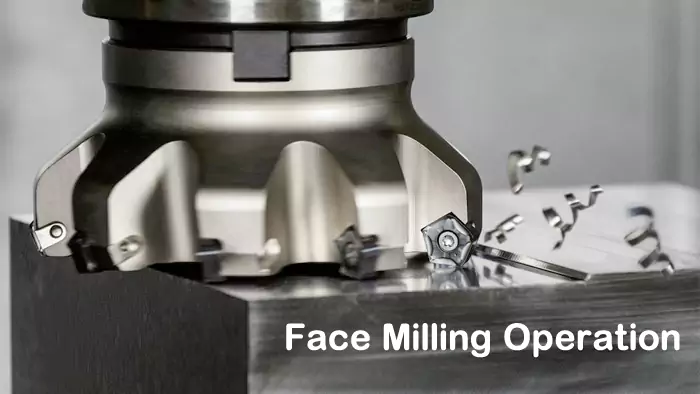
At Allied Metal, creating flat surfaces is a daily task in our CNC machining operations. Whether we're prepping raw stock or finishing a critical mating surface for an engineer like David, face milling is one of our most important go-to processes. In my understanding face milling is a quick and efficient way to produce flat surfaces using tools that cut with both their ends and sides. It's fundamental for so many applications. It's often used to prep parts for machining, assembly, or mating. Understanding how it works, what tools to use, and how it compares to other milling techniques is key for any engineer or designer. Once you understand the tools and how it differs from other methods, it opens up many machining possibilities. Let's explore this essential machining operation.
How Exactly Does Face Milling Achieve a Flat Surface?
You know face milling creates flat surfaces, but what's the mechanical process? How does the cutter interact with the material to produce that precise, level plane?
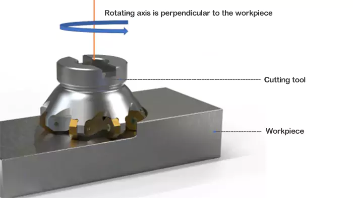
Face milling works by rotating a cutter with teeth on its face and periphery perpendicular to the workpiece. As it feeds across, the teeth remove material, generating a flat surface.
Diving Deeper into the Mechanics of Face Milling
Face milling is a highly effective method for producing flat surfaces on a workpiece, and understanding its mechanics is straightforward. Imagine a circular cutter, almost like a large, specialized disk, equipped with multiple cutting teeth or inserts around its circumference (periphery) and often on its "face" or bottom surface.
- Cutter Orientation and Rotation: The crucial aspect of face milling is that the axis of rotation of the cutter is perpendicular (at a 90-degree angle) to the surface being machined. The cutter spins at a programmed speed (RPM).
- Cutting Action: As the face mill rotates, the cutting edges on both its periphery and its face engage the material.
- The peripheral cutting edges do some of the initial shearing as the cutter enters and exits the material (if the cut is wider than the cutter's radius but narrower than its diameter).
- The cutting edges on the face of the tool (especially the corner radius or chamfer of the inserts and the wiper flat, if present) are primarily responsible for generating the final flat surface as the tool feeds across the workpiece. My insight about tools cutting with "both their ends and sides" highlights this combined action.
- Feed Movement1: The workpiece (on a moving table) or the cutting head itself (on some machines) is fed linearly at a controlled rate, typically perpendicular to the cutter's axis but parallel to the desired flat surface. This feed movement allows the rotating cutter to sweep across the entire area to be machined.
- Chip Formation: Each cutting tooth takes a small bite out of the material, producing chips. The geometry of the cutting inserts and the cutting parameters (speed, feed, depth of cut) determine the chip thickness and shape. Efficient chip removal is important to prevent re-cutting and to ensure a good surface finish.
The result of this combined rotational cutting and linear feed is a progressively generated flat surface. The quality of this surface depends on factors like the cutter design (especially wiper inserts), machine rigidity, and cutting parameters.
What Are the Primary Uses of Face Milling in Manufacturing?
Creating flat surfaces is a broad goal. In what specific situations or for what types of parts is face milling the preferred and most effective machining operation?
Face milling is primarily used for producing large, flat mating surfaces, squaring up blocks of raw material, preparing stock for subsequent machining operations, and achieving precise surface finishes.
Diving Deeper into Face Milling Applications
Face milling is one of the most fundamental and widely used milling operations due to its efficiency in creating flat surfaces, which are essential for countless mechanical components. As I've shown before, this is usually a preparatory step, but it's also critical for final part characterization. Here are some of the main uses an engineer like David would encounter:
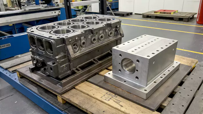
- Creating Flat Mating Surfaces2:
- This is perhaps the most common application. Many components need to bolt or fit precisely against other parts. Face milling ensures these interfacing surfaces are perfectly flat and often perpendicular or parallel to other features, guaranteeing proper assembly and function. Examples include engine block decks, cylinder heads, machine bases, and fixture mounting surfaces.
- Squaring Up Raw Material3:
- Raw stock (like bar stock or plate) often doesn't come with perfectly flat or square sides. The first operation in machining a part from such stock is frequently face milling all six sides to create a precise, square or rectangular blank, ready for further machining operations. This establishes accurate datums.
- Preparing Stock for Other Operations:
- Face milling is used to quickly remove a consistent layer of material from a surface to achieve a desired thickness or to clean up a rough cast or forged surface before more detailed machining. This ensures subsequent operations start from a known, flat reference.
- Producing a Specific Surface Finish:
- While rough face milling is for bulk material removal, finish face milling, often with specialized "wiper" inserts, can produce very smooth and flat surfaces that meet specific Ra (surface roughness) requirements, sometimes eliminating the need for grinding.
- Machining Large Surface Areas:
- For components with large surface areas that need to be flat, face milling with a large-diameter cutter is much more efficient than trying to achieve flatness with multiple passes of a smaller end mill.
- Creating Steps or Shoulders:
- While end mills are also used for steps, a face mill can be employed to machine a wide step or shoulder efficiently if the geometry allows.
In essence, whenever a flat, true surface is required on a workpiece, face milling is a primary candidate operation due to its speed, efficiency, and the quality of the surface it can produce.
Are There Different Types or Variations of Face Milling Operations?
Is face milling always the same basic operation, or are there different techniques or approaches used depending on the specific requirements of the job?
Yes, variations include conventional versus climb milling, roughing versus finishing passes, and specialized techniques like high-feed face milling, each tailored for different outcomes like material removal or surface quality.
Diving Deeper into Face Milling Techniques
While the fundamental principle of face milling (cutter axis perpendicular to the surface) remains constant, there are variations and specific techniques employed to optimize the process for different materials, desired outcomes, and machine capabilities. For engineers, understanding these nuances can be helpful when discussing manufacturing with a shop like Allied Metal.
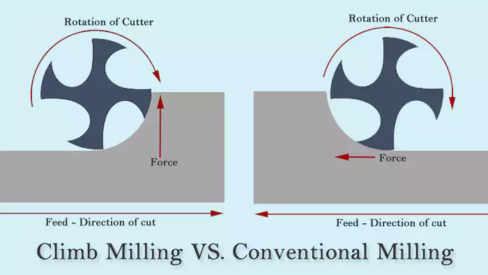
- Conventional Milling (Up Milling) vs. Climb Milling (Down Milling):
- This refers to the relationship between the cutter's rotation and the feed direction.
- Conventional Milling: The cutter rotates against the direction of feed. Chip thickness starts at zero and increases. This can cause the tool to rub before it bites, potentially leading to work hardening and more tool wear, but it can be preferred on manual machines or machines with backlash in the lead screws as it tends to pull the table into the cutter.
- Climb Milling: The cutter rotates with the direction of feed. Chip thickness starts at maximum and decreases. This generally results in better surface finish, longer tool life (as the tool bites immediately, reducing rubbing), and more efficient cutting. Most modern CNC machines are rigid enough to handle climb milling, and it's often the preferred method for face milling.
- Roughing vs. Finishing Passes:
- Rough Face Milling: The primary goal is to remove a large volume of material quickly. This typically involves a greater depth of cut, a robust cutter, and a feed rate optimized for material removal rate (MRR)4 rather than an exquisite surface finish.
- Finish Face Milling: The goal is to achieve the final desired surface flatness, dimensional accuracy, and surface finish. This usually involves a lighter depth of cut, often higher spindle speeds, optimized feed rates, and sometimes specialized cutting inserts (like wiper inserts) to produce a very smooth surface.
- Full Width vs. Partial Width Cutting:
- Full Width: The diameter of the face mill is larger than the width of the surface being machined, so the entire surface is cut in a single pass.
- Partial Width (or Step-Over): The cutter diameter is smaller than the surface width, requiring multiple overlapping passes to machine the entire area. The amount of step-over (how much each pass overlaps the previous one) affects the surface pattern and efficiency.
- High-Feed Face Milling:
- This is a specialized technique using face mills with unique insert geometries (often with large lead angles and small corner radii) designed for very high feed rates at relatively shallow axial depths of cut. It’s excellent for rapid material removal in roughing operations, especially on powerful and rigid machines.
These variations allow machinists to tailor the face milling process to achieve specific objectives efficiently.
Face Milling vs. End Milling: What Are the Key Distinctions?
Both face mills and end mills are common in a machine shop. How do these two fundamental milling operations and their respective tools differ in application and capability?
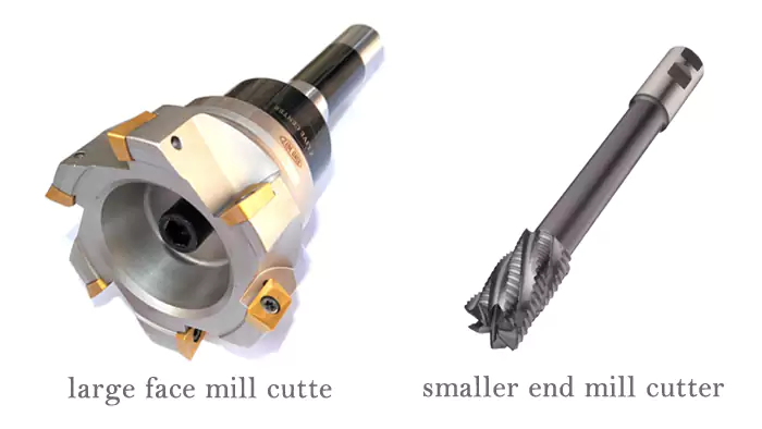
Face milling uses large-diameter cutters with axis perpendicular to machine broad flat surfaces. End milling uses smaller, versatile cutters for pockets, slots, profiles, and intricate 2D/3D features.
Diving Deeper into Comparing Face Mills and End Mills
While both face milling and end milling are methods of removing material with a rotating cutter, they are distinct in their primary applications, tool geometry, and how they engage the workpiece. Understanding these differences is crucial for engineers like David when designing parts and considering how they will be manufactured.
| Feature | Face Milling | End Milling |
|---|---|---|
| Primary Purpose | Creating large, flat surfaces; squaring stock; preparing surfaces. | Creating pockets, slots, contours, profiles, steps, holes, 3D surfaces. |
| Cutter Axis | Perpendicular to the machined surface. | Typically perpendicular to the machined surface, but can be used for side cutting. |
| Cutting Edges Used | Primarily on the face (bottom) and periphery of the cutter. My insight about tools cutting with "ends and sides" applies here. | On the end (tip) and periphery (flutes) of the cutter. |
| Typical Cutter Diameter | Larger (e.g., 2 inches / 50mm up to very large diameters). | Smaller (e.g., 1/8 inch / 3mm up to 1-2 inches / 25-50mm typically, but can vary). |
| Tool Geometry | Often indexable insert cutters with multiple inserts; sometimes solid. | Typically solid HSS, cobalt, or carbide; sometimes indexable for larger diameters. |
| Depth of Cut (Axial) | Can take significant axial depths for roughing, or light for finishing. | Varies greatly; can be shallow for profiling or deep for pocketing/slotting (in steps). |
| Width of Cut (Radial) | Often aims for a wide cut, sometimes wider than the tool radius. | Can range from full slotting (width = diameter) to light profiling (small radial engagement). |
| Machine Type | Can be done on vertical or horizontal mills, CNC machining centers. | Most common on vertical mills and CNC machining centers. |
Key Distinctions Summarized:
- Scale of Surface: Face milling is for broad, flat surfaces. End milling is generally for more localized features or smaller surfaces, though it can also produce flat floors in pockets.
- Tool Design: Face mills are designed to sweep a wide area. End mills are more like "routers" for metal, capable of plunging, side cutting, and contouring.
- Versatility: End milling is generally more versatile for creating a wider variety of geometric features. Face milling is more specialized for creating flatness efficiently.
Often, both operations are used on the same part. For example, a block might first be face milled to make it square and flat, and then end mills might be used to create pockets, holes, and contours on those flat surfaces.
How Does Face Milling Differ Fundamentally from Peripheral Milling?
We know face milling cuts with the tool's face and edges, axis perpendicular. How does this compare to peripheral milling, where the tool's side does the work?
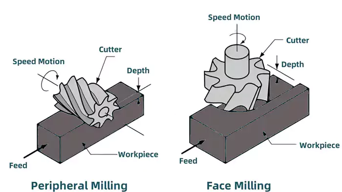
In face milling, the cutter's axis is perpendicular to the machined surface; cutting uses face/peripheral edges. In peripheral milling, the axis is parallel; cutting uses only peripheral edges.
Diving Deeper into the Core Operational Differences
The fundamental difference between face milling and peripheral milling lies in the orientation of the cutting tool's axis of rotation relative to the workpiece surface being machined, and consequently, which parts of the cutter are doing the primary work.
Face Milling:
- Cutter Axis: Perpendicular (90°) to the flat surface being generated.
- Cutting Edges: Cutting is performed by teeth or inserts located on both the face (end/bottom) of the cutter and its periphery (circumference). My insight that face milling tools cut with "both their ends and sides" is a good way to remember this. As the cutter sweeps across the workpiece, the face edges generate the primary flat surface, while the peripheral edges might engage at the sides of the cut or when entering/exiting.
- Chip Formation: Chips are typically formed by the cutting edges on the face and are often thinner and wider.
- Primary Application: Creating large, flat surfaces efficiently.
- Example Tool: A face mill cutter (often with indexable inserts).
Peripheral Milling (also known as Plain Milling):
- Cutter Axis: Parallel to the flat or contoured surface being generated.
- Cutting Edges: Cutting is performed exclusively by teeth or inserts located on the periphery (circumference) of the cutter. The end face of the cutter (unless it's an end mill being used for plunging) is generally not involved in cutting the primary surface.
- Chip Formation: Chips are formed by the peripheral cutting edges as they rotate into the material. Chip thickness varies depending on whether it's conventional (up) or climb (down) milling.
- Primary Applications: Creating slots (slot milling), machining edges or shoulders (side milling), forming contoured surfaces with form cutters, or machining wide flat surfaces (slab milling, using a wide cylindrical cutter).
- Example Tools: Slab mill, side milling cutter, slotting cutter, form cutter, plain end mill (when cutting only with its side).
Key Distinction for David:
When David is visualizing how a feature will be machined, if it's a broad flat top surface, it's likely face milling. If it's a slot cut into the side, or a profile along an edge, it's likely some form of peripheral milling (often with an end mill). The choice of operation directly impacts the type of cutter selected and the machine setup. While an end mill can be used for face milling small areas (especially its bottom face if it's center-cutting), dedicated face mills are much more efficient for larger surfaces.
Face Milling vs. Slab Milling: Are They the Same Thing?
Both face milling and slab milling can produce flat surfaces. Are these just different names for the same operation, or are there distinct differences between them?
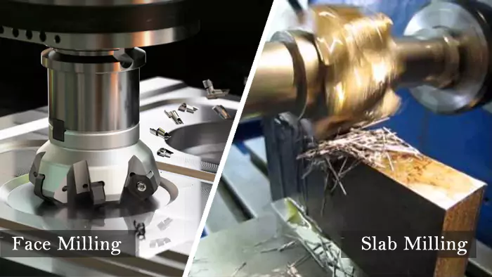
No, they are different. Face milling uses a cutter with its axis perpendicular to the surface. Slab milling is a type of peripheral milling using a wide, cylindrical cutter with its axis parallel.
Diving Deeper into Face Milling and Slab Milling
While both face milling and slab milling can be used to create flat surfaces, they are distinct milling operations that differ in cutter geometry5, cutter orientation, and the type of machine typically used. For an engineer in manufacturing like David, understanding this distinction is important when considering manufacturing options for large flat components.
Face Milling:
- Cutter Type: Uses a face mill cutter. This cutter has multiple teeth (often indexable inserts) on its face (the end perpendicular to its axis) and often on its periphery.
- Cutter Axis: The axis of rotation is perpendicular to the surface being machined.
- Machine Type: Commonly performed on vertical milling machines6 or vertical CNC machining centers, but can also be done on horizontal machines with a right-angle head or if the workpiece is oriented appropriately.
- Cutting Action: Cutting is done by the inserts on the face and periphery of the cutter as it sweeps across the workpiece.
- Application: Efficiently creating flat surfaces of various sizes, squaring blocks, preparing stock. It's very versatile. My insight about face milling being quick and efficient for flat surfaces applies directly.
Slab Milling (a type of Peripheral Milling):
- Cutter Type: Uses a "slab mill" or "plain milling cutter." This is a cylindrical cutter with straight or helical teeth on its periphery. It does not have cutting teeth on its ends.
- Cutter Axis: The axis of rotation is parallel to the surface being machined.
- Machine Type: Primarily performed on horizontal milling machines, where the cutter is mounted on an arbor that spans between the machine spindle and an outboard support.
- Cutting Action: Cutting is done solely by the teeth on the periphery of the rotating cutter as the workpiece is fed past it.
- Application: Primarily used for machining large, wide, flat surfaces, often in a single pass if the cutter is wide enough. It can be very efficient for heavy material removal on suitable machines.
Key Differences Summarized:
| Feature | Face Milling | Slab Milling (Peripheral Milling) |
|---|---|---|
| Cutter Axis | Perpendicular to surface | Parallel to surface |
| Cutting Edges | Face and Periphery | Periphery only |
| Typical Machine | Vertical Mills, CNC Machining Centers | Horizontal Milling Machines |
| Common Cutter | Face Mill (often indexable) | Slab Mill (cylindrical, arbor-mounted) |
So, while both can produce a flat surface, the way they achieve it and the typical machinery involved are quite different. Slab milling is a more traditional method often associated with horizontal mills for heavy stock removal on wide surfaces, while face milling is a more versatile operation common on both vertical and horizontal CNC machines for a wide range of flat surfacing tasks.
How Do You Choose the Best Cutting Tool for Effective Face Milling?
The face mill itself is key to success. What factors should you consider when selecting the right cutter and inserts for your face milling operation?
Choose based on workpiece material, surface width, required finish, and machine capability. Consider cutter diameter, number of teeth/inserts, insert geometry, grade, and coating for optimal results.
Diving Deeper into Face Mill Selection
Selecting the ideal cutting tool for face milling is crucial for achieving good surface finish, high material removal rates, and good tool life. It's not just about picking any face mill; several factors need consideration. For engineers or designers specifying parts, understanding these factors can help in discussions about manufacturability.
- Cutter Diameter:
- The cutter diameter should ideally be larger than the width of the surface being machined if you want to finish it in a single pass. A common rule of thumb is for the cutter diameter to be about 1.2 to 1.5 times the width of cut.
- If the surface is wider than available cutter diameters, multiple overlapping passes will be needed.
- Larger diameters can remove material faster but require more machine power and rigidity.
- Number of Teeth/Inserts:
- More teeth (higher density of inserts) generally allow for higher feed rates, increasing productivity. However, too many teeth in a small diameter can lead to chip clogging issues, especially in gummy materials.
- Fewer teeth (coarse pitch) provide more chip clearance, which can be better for roughing or machining materials that produce long, stringy chips.
- The number of effective cutting edges influences the feed per minute calculation.
- Insert Geometry, Grade, and Coating:
- Geometry: Inserts come with various rake angles, clearance angles, edge preparations (honed, sharp), and chipbreaker designs. These should be matched to the workpiece material (e.g., positive rake for aluminum, more negative rake for harder steels or interrupted cuts).
- Wiper Inserts: Special inserts with a small flat edge that "wipes" the surface as it cuts, producing a much smoother finish at higher feed rates. Essential for high-quality finishing.
- Grade (Carbide Type): Different carbide grades offer different balances of hardness, toughness, and wear resistance, optimized for specific material groups (e.g., ISO P for steels, K for cast iron, M for stainless, N for non-ferrous like aluminum).
- Coating: Modern coatings (TiN, TiCN, TiAlN, AlTiN, etc.) significantly enhance hardness, wear resistance, and reduce friction, allowing for higher cutting speeds and longer tool life. The coating should be matched to the workpiece material.
- Geometry: Inserts come with various rake angles, clearance angles, edge preparations (honed, sharp), and chipbreaker designs. These should be matched to the workpiece material (e.g., positive rake for aluminum, more negative rake for harder steels or interrupted cuts).
- Cutter Body Material and Design7:
- Most modern face mills for production use indexable inserts held in a steel or alloy body. The body must be rigid and provide secure insert clamping.
- Through-tool coolant capability can be very beneficial.
- Machine Tool Capability:
- Ensure your machine has sufficient spindle power, torque, and rigidity to effectively use the selected face mill, especially larger diameters or those intended for aggressive cutting.
My experience at Allied Metal confirms that investing in good quality face mills and appropriate inserts pays off in terms of performance, surface finish, and overall efficiency.
What Cutting Speeds Are Typically Used in Face Milling Operations?
You've chosen your face mill. Now, how fast should it run? Determining the right cutting speed is vital for tool life, surface quality, and overall efficiency.
Cutting speed (SFM or m/min) for face milling depends heavily on workpiece material and tool (insert) material. Aluminum is cut at high speeds, steels much slower. Always consult manufacturer data.
Diving Deeper into Face Milling Speeds
Cutting speed ($V_c$) in face milling, just like in other milling operations, is a critical parameter that dictates how fast the cutting edges of the inserts move across the workpiece surface. It's usually expressed in Surface Feet per Minute (SFM) or meters per minute (m/min). This $V_c$ value is then used to calculate the spindle speed (RPM) based on the cutter's effective diameter.
Key Factors Influencing Cutting Speed Choice:
- Workpiece Material: This is the primary driver.
- Aluminum Alloys: Can be face milled at very high cutting speeds (e.g., 800-3000 SFM or even higher with specialized tooling).
- Mild/Low Carbon Steels: Moderate speeds (e.g., 300-800 SFM).
- Alloy Steels / Tool Steels (Annealed): Lower speeds (e.g., 200-500 SFM).
- Stainless Steels: Generally require lower speeds than carbon steels (e.g., 150-450 SFM) due to their toughness, work-hardening tendency, and poor thermal conductivity.
- Cast Iron: Speeds vary with grade (e.g., 200-600 SFM).
- High-Temperature Alloys (e.g., Inconel): Very low speeds (e.g., 50-150 SFM).
- Cutting Tool Material (Insert Grade and Coating):
- Uncoated Carbide: Base speeds.
- Coated Carbide (TiN, TiCN, TiAlN, etc.): Allow for significantly higher cutting speeds (often 25-50%+ increase or more) compared to uncoated carbide, due to improved hardness, wear resistance, and reduced friction. The specific coating dictates the optimal speed range.
- Ceramics, CBN, PCD: Can operate at extremely high speeds but are for specialized applications.
- Operation Type (Roughing vs. Finishing):
- For roughing, speeds might be slightly reduced from the maximum to prioritize tool life with heavier depths of cut.
- For finishing, speeds might be optimized (often at the higher end of the recommended range for the material/tool) to achieve the best surface finish, sometimes in conjunction with wiper inserts.
- Machine Rigidity and Coolant:
- A rigid machine setup allows for more aggressive parameters. Effective coolant application helps dissipate heat, enabling higher speeds.
Finding Recommendations:
The best source for recommended cutting speeds is always the cutting tool/insert manufacturer's catalog or technical data. They provide specific SFM or m/min ranges for their products cutting various materials. These are starting points, and experienced machinists like those at Allied Metal will fine-tune them based on the specific machine, setup, and observed cutting conditions. For David, providing material specifications helps us select appropriate starting parameters.
What Are Some Key Tips for Achieving Optimal Results in Face Milling?
Knowing the theory is one thing, but what practical advice can help you get the best performance, surface finish, and tool life from your face milling operations?
Use a cutter diameter larger than the cut width if possible, choose appropriate insert geometry and grade, employ climb milling on CNCs, ensure rigid setup, and optimize speeds/feeds.

Diving Deeper into Face Milling Best Practices
Achieving excellent results in face milling involves more than just selecting a tool and hitting "cycle start." It requires attention to several details. Here are some of the key tips we follow at Allied Metal, and of course, you may need them when designing parts or discussing manufacturing:
- Cutter Selection and Positioning:
- Diameter: As mentioned, ideally, the face mill diameter should be about 20-50% larger than the width of the surface being cut to allow for a single pass and optimal entry/exit of the inserts.
- Positioning: For best results and to minimize burr formation, position the centerline of the face mill slightly off-center from the workpiece centerline, especially when the cutter is not much wider than the part. This influences how the inserts enter and exit the cut.
- Employ Climb Milling (Down Milling):
- On modern, rigid CNC machines, climb milling is generally preferred for face milling. It typically results in better surface finish, longer tool life (reduced rubbing), and more efficient chip formation. The cutting forces also tend to hold the workpiece down against the table.
- Insert Choice is Critical:
- Use the correct insert geometry, grade, and coating for the specific workpiece material. Positive rake inserts are good for aluminum and non-ferrous, while more neutral or slightly negative rakes might be used for steels or interrupted cuts.
- Wiper inserts are highly recommended for finishing passes if a very smooth surface is required. A single wiper insert in a multi-tooth cutter can dramatically improve finish.
- Ensure Machine and Workholding Rigidity:
- Face milling, especially with larger cutters or aggressive parameters, generates significant cutting forces. A rigid machine tool and secure workholding are essential to prevent vibration, chatter, and ensure accuracy. Any looseness will lead to poor surface finish and reduced tool life.
- Optimize Cutting Parameters (Speeds, Feeds, Depth of Cut):
- Start with manufacturer recommendations and adjust based on observation. Don't be afraid to adjust feed rates to achieve good chip formation.
- For roughing, aim for a good depth of cut (within tool/machine limits). For finishing, use a lighter depth of cut.
- Chip Evacuation and Coolant:
- Ensure chips are effectively cleared from the cutting zone to prevent re-cutting.
- Use appropriate coolant (flood, mist, or even air blast for some materials like cast iron) to control temperature, reduce friction, and aid chip removal.
- Regularly Inspect Inserts:
- Check inserts for wear or chipping and rotate or replace them as needed. Running with dull or damaged inserts will lead to poor results and can damage the cutter body or workpiece.
Following these tips, which are part of our daily practice, helps ensure consistent, high-quality results from face milling operations.
Conclusion
Face milling efficiently creates flat, precise surfaces essential for many parts. Proper tool selection, parameters, and techniques are key to optimizing this fundamental machining operation.
- Learning about Feed Movement is essential for mastering machining processes and improving productivity in manufacturing. ↩
- Explore this link to learn about techniques and tips for achieving precision in flat mating surfaces, crucial for assembly. ↩
- Discover effective methods for squaring raw materials, essential for ensuring accuracy in subsequent machining operations. ↩
- Learn about MRR to optimize machining processes and improve efficiency in manufacturing. ↩
- Understanding cutter geometry is crucial for optimizing milling operations; this resource will provide valuable insights. ↩
- Learn about vertical milling machines, their features, and how they are utilized in various milling operations. ↩
- The material and design of cutter bodies play a vital role in machining efficiency and tool performance. Learn more about this topic for better machining outcomes. ↩
