Editor’s Note: Last modified on November 5, 2025, by Lucy
Need a custom part to fit perfectly every time? A tiny error of just 0.01mm can cause a hydraulic leak or a bearing to fail. Understanding precision machining tolerances is the only way to guarantee your part’s function.
What is precision machining tolerance?
If we have a product in mind, especially a precision machined product, there is one issue we must consider at some point before you commit to the mass production stage and that is – tolerances.
Precision machining tolerance is the total permissible variation in a part’s dimension. It’s the “acceptable range” between the maximum and minimum limits that an engineer defines on a drawing to ensure a part functions correctly.

In simple terms, tolerances are the allowable limits for variation in a part’s dimensions. Think of them as the “wiggle room” in machining—too tight, and you might drive up costs; too loose, and the part might not fit or function properly. For custom non-standard parts, this is especially critical. From my experience, I’ve seen projects go south because of overlooked tolerances, leading to assembly issues or even safety hazards. Common types include linear tolerances (like ±0.1 mm for lengths) and geometric tolerances (such as flatness or concentricity). Standards like ISO 2768 or ASME Y14.5 provide guidelines, but it’s all about balancing precision with practicality.
What is the role of tolerances in precision machining?
We all know that in theory, perfect parts don’t exist. Every machining process—whether CNC turning, milling, or grinding—introduces small dimensional deviations. The key is to keep those deviations within a specified range.
In CNC machining, tolerances determine how closely a finished part matches the CAD drawing. They directly affect interchangeability, assembly, and final performance. For example, a shaft that’s just 0.02 mm oversize might seize in a bearing, while one that’s 0.02 mm undersize could cause vibration and premature wear.

Tighter tolerances usually mean more machining time, higher tool wear, and stricter quality control—so balancing functional needs with manufacturing feasibility is crucial. Most customers know this intuitively: the smaller the tolerance, the higher the cost.
Key Factors Influencing Tolerance Selection
When you’re specifying tolerances, consider the material, machining process, and end-use. For instance, aluminum might handle tighter tolerances than plastics due to thermal expansion. Processes like CNC milling can achieve tolerances as fine as ±0.025 mm, while turning might cap at ±0.05 mm. Always ask: What’s the part’s role? A bearing surface needs tighter control than a cosmetic cover. Over the years, I’ve advised teams to start with standard tolerances and only tighten them where necessary—it saves time and money without compromising quality.
What Is the Tolerance for Precision Machining?
When people ask, “What’s a standard machining tolerance?”, the short answer is: it depends on the process, material, and precision level required.
But in general CNC work, most well-calibrated machines hold tolerances around ±0.005 inch (±0.13 mm) without difficulty.
Here’s a quick breakdown from everyday shop practice:
- CNC Router: typically holds ±0.005″ (0.13 mm).
- Lathe (Turning): around ±0.005″ (0.13 mm) for most metals and plastics.
- Router for Gasket Cutting Tools: looser, about ±0.030″ (0.76 mm), since the materials are softer and more flexible.
- 3-Axis CNC Milling: ±0.005″ (0.13 mm) is a good benchmark for aluminum, brass, or mild steel.
- 5-Axis CNC Milling: also around ±0.005″ (0.13 mm), though complex geometry may call for local tolerance adjustments.
- Engraving: usually maintained at ±0.005″ (0.13 mm), depending on depth and tool condition.
- Rail or Long-Part Cutting: ±0.030″ (0.76 mm) is typical due to thermal and vibration effects along longer runs.
Of course, these are general production tolerances, not the tightest a shop can achieve. With temperature control, precision tooling, and fine finishing (like grinding or honing), we can routinely hold down to ±0.001″ (0.025 mm) or even tighter on critical dimensions.
The key takeaway is this:
👉 Always define tolerances based on how the part functions—not just what the machine can technically achieve. Chasing ultra-tight tolerances everywhere can drive up cost and lead time for no real benefit.
Types of precision machining tolerances in manufacturing
On the shop floor, we see these callouts every day. Here’s what they actually mean in practice for an engineer or designer.
1. Bilateral Tolerance
This is the classic “plus or minus” tolerance. It’s symmetrical.
- Example: 20.00 mm ±0.05 mm
- What it means: The part is acceptable if it’s anywhere between 19.95 mm and 20.05 mm. It’s a simple, common tolerance for non-critical features.
2. Unilateral Tolerance
This is where the error is only allowed to go in one direction from the nominal size.
- Example: 20.00 mm +0.00 / -0.05 mm
- What it means: This tells my machinists that the part can never be over 20.00 mm, but it can be slightly smaller (down to 19.95 mm). We see this all the time for holes, as it ensures a pin or shaft of a specific size will always fit.
3. Limit Tolerance
This is my personal favorite because it’s the clearest and safest. Instead of making the machinist do math, the drawing simply states the maximum and minimum allowed sizes.
- Example: 19.95 – 20.00 mm
- What it means: The part is good if it measures anywhere within this range. There’s no ambiguity.
4. Geometric Dimensioning and Tolerancing (GD&T)
This is the most advanced and powerful type of tolerancing. It’s a whole symbolic language that doesn’t just control size; it controls the part’s shape and relationship to other features. This is what we use for complex, high-performance parts.
5. Flatness
This is a common GD&T callout. A tolerance for flatness ensures a surface is perfectly flat, with no waviness or bowing. This is critical for gaskets and sealing faces.
6. Perpendicularity
This is another GD&T callout. It ensures one feature (like a face or a hole) is perfectly 90 degrees to another feature (the “datum”). This is essential for parts that need to align perfectly in an assembly.
From the Shop Floor: A Case Study in Applying Critical Tolerances
All those tolerance types might seem academic, but let me show you how they come together on a single, high-stakes part. We recently manufactured a piston for an aerospace hydraulic actuator. This is a part where failure is not an option, and the tolerances on the engineering drawing tell the whole story.
When an engineer designs a part like this, they’re not just defining a shape; they’re defining its function through tolerances.
The "Must-Know" Tolerances for This Part:
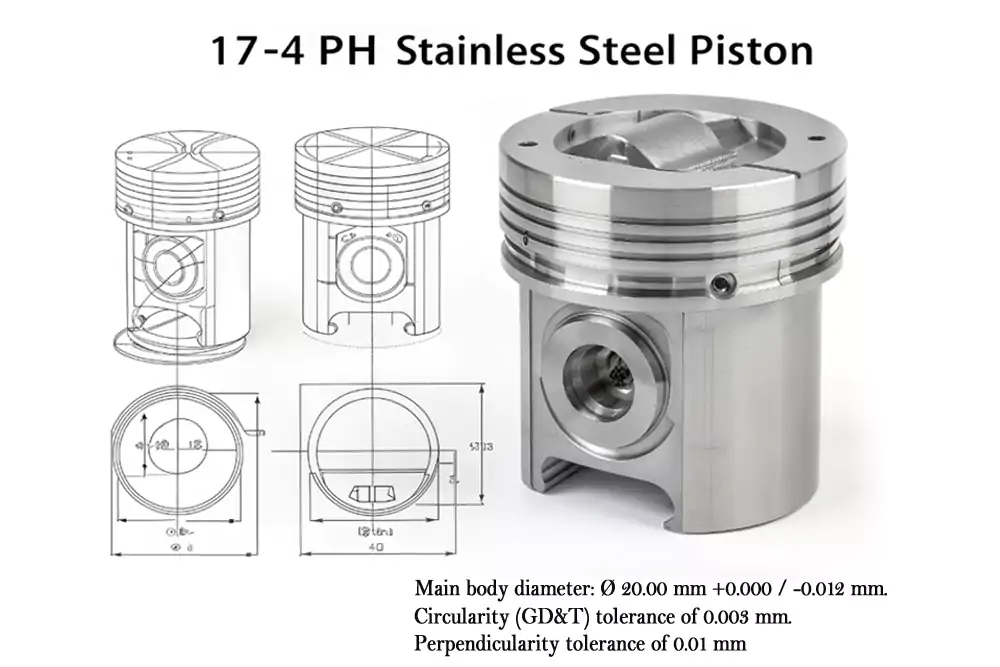
- Part Name: Aerospace Actuator Piston
- Material: 17-4 PH Stainless Steel (Hardened to H900)
- Key Process: CNC Turn-Mill Center (to machine it all in one setup)
Below is a detailed description of the three critical tolerances for this part:
- The Limit Tolerance (for the Seal):
- The Callout: The main body diameter was Ø 20.00 mm, with a tolerance range of +0.000 / -0.012 mm. This is a form of Unilateral Tolerance (like we just discussed).
- Why it Matters (The Shop-Floor Truth): This isn’t an arbitrary number. This diameter is where a hydraulic seal sits. If the part is even a fraction over 20.00 mm, the seal won’t fit. If it’s under the 19.988 mm limit, the high-pressure (3000 PSI) fluid will blow right past it. We had to use a special, ultra-precise turning insert and measure this in our climate-controlled inspection room to get it right.
- The Geometric Tolerance (for the Shape):
- The Callout: That same 20mm diameter also had a Circularity (GD&T) tolerance of 0.003 mm.
- Why it Matters: This is what I tell new engineers all the time: a part can be “in spec” on its diameter but still be useless. The CMM could measure the diameter as 19.995 mm, but if the part is “egg-shaped” (out-of-round), the seal will leak. This circularity callout forces us, the machinist, to ensure the part is perfectly round within 3 microns. This is not a “maybe”; it’s a “must.”
- The GD&T Tolerance (for the Alignment):
- The Callout: The front face of the piston had a Perpendicularity tolerance of 0.01 mm relative to the central axis of the bore (the “datum”).
- Why it Matters: This piston pushes a rod. If that front face is even slightly angled, it will push the rod crooked. Over thousands of cycles, this side-loading will destroy the actuator. This GD&T callout (from point #6) ensures the face is perfectly 90 degrees to the direction of travel, so it pushes straight, every single time.
- The Limit Tolerance (for the Seal):
The Result:
We delivered a part that met every single callout. The client’s assembly was successful, and it passed all its high-pressure cycle tests. That’s the real purpose of tolerances. It’s not just about making a part; it’s about guaranteeing its function.
Common Pitfalls and Best Practices
From my two decades in the shop, I’ve seen folks over-specify tolerances, driving costs through the roof. A classic mistake? Applying ±0.01 mm to non-critical features—it’s like using a sledgehammer to crack a nut. Instead, focus on the 80/20 rule: Tighten tolerances only where function demands it. Use statistical process control to monitor consistency, and always validate with first-article inspections. For custom parts, build in a buffer for tooling variations; it’s a lifesaver when deadlines loom.
Summary:
At the end of the day, precision machining tolerances are about smart compromises. As an old hand in the factory, I’d say keep it simple: Communicate clearly with your team, leverage standards, and learn from each project. If you take away one thing, let it be this—tolerances aren’t just numbers; they’re the bridge between design and reality. Need more insights? Feel free to reach out—we’re here to help you nail those specs every time.
Need Help Defining the Right Tolerances for Your Parts?
Upload your part files or send us your drawings, and we’ll review them for manufacturing feasibility, tolerance optimization, and cost efficiency—all within 24 hours.
