Many projects fail because the driveshaft was treated like a simple rod. I have seen delays, vibration issues, and field failures caused by early design shortcuts.
A custom driveshaft is built through a clear process: define load and speed, design dimensions and tolerances, choose the right material, control machining and heat treatment, then verify balance and runout. Each step affects durability, noise, and safety.
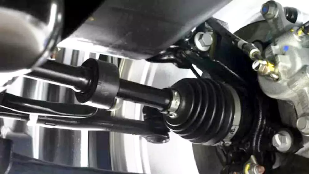
A driveshaft looks simple. It is not. It connects power, motion, and reliability. Small mistakes grow fast at high RPM. If you are new to shaft applications, it also helps to understand what a motor shaft is and how it differs from a full power transmission shaft. Let’s break it down step by step.
When Are Application Requirements and Design Fundamentals Critical?
I often see teams reuse an old shaft design. That works until torque rises or space shrinks. Then vibration, noise, or early wear shows up.
You need a custom driveshaft when torque, speed, space, or weight limits go beyond standard parts. Correct load calculation, critical speed control, and tight runout limits keep the system stable and safe.
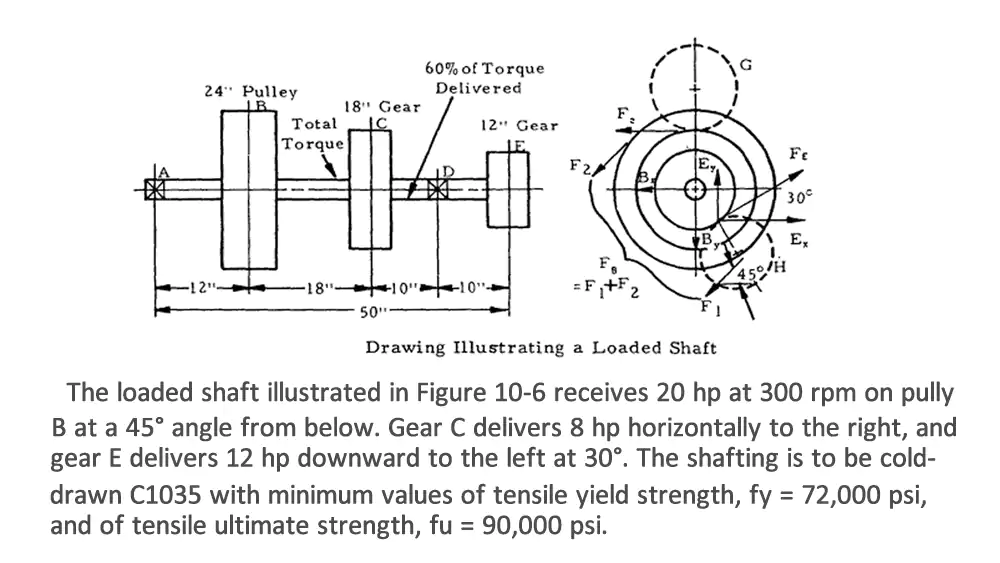
I always start with the job the shaft must do. I ask about peak torque, normal torque, shock loads, and duty cycle. These numbers drive everything. A shaft for an electric vehicle sees high instant torque. A motorcycle shaft sees fast RPM changes. An industrial system may rely on principles similar to those used in transmission shafts, where load stability and alignment are critical.
Load and Torque Calculation
Torque defines shear stress. Bending comes from misalignment and overhung loads. I use both to size diameter. Thin shafts save weight. They also twist more. That can hurt response in servo systems.
| Parameter | Why It Matters | Typical Source |
|---|---|---|
| Peak Torque1 | Sets minimum diameter | Motor or engine data |
| Continuous Torque | Affects fatigue life | Duty cycle study |
| Shock Factor | Covers sudden loads | Application type |
| Safety Factor | Adds design margin | Industry standard |
Critical Speed2 and Vibration
Every shaft has a speed where it wants to bend and whirl. That is critical speed. I keep operating speed well below the first critical speed. If not, vibration rises fast and bearings fail early.
Dimensions, Tolerance, and Balance
Length, diameter, and wall thickness work together. Long shafts need larger diameters or tubes. I also control runout tightly. Poor straightness causes imbalance. For high speed shafts, I often specify G6.3 or even G2.5 balancing grade. Many of these design rules also apply when working through a full custom shaft manufacturing guide, where application data drives geometry.
How Do Material Choices Affect Driveshaft Performance?
I once replaced a steel shaft with aluminum in a test rig. The machine felt more responsive right away. Later we had to increase diameter to keep stiffness high.
The best driveshaft material depends on torque, speed, environment, and weight targets. Alloy steel handles high torque, aluminum reduces weight, stainless resists corrosion, and carbon fiber suits extreme speed.
Material is always a trade-off. There is no universal “best.” In automotive and EV projects, this decision is often part of a broader custom automotive shaft machining strategy where strength, weight, and cost must stay balanced.
Alloy Steel
I use 4140 or 43403 for high torque. These steels respond well to heat treatment. They offer high strength and good fatigue life. They are heavier, but very reliable.
Aluminum
Aluminum works well in EVs and light vehicles. Lower density reduces rotating mass. That improves efficiency and response. I increase diameter to keep stiffness high. Surface wear areas may need sleeves.
Stainless Steel
In food machinery or marine use, corrosion matters more than weight. Stainless steels like 17-4PH give good strength with corrosion resistance.
Carbon Fiber
For very high speed systems, carbon fiber tubes shine. They are light and have high damping. Cost is higher. End fittings must be bonded carefully.
| Material | Strength | Weight | Cost | Typical Use |
|---|---|---|---|---|
| 4140 Steel | High | High | Medium | Heavy-duty industrial |
| Aluminum 7075 | Medium | Low | Medium | EV and light vehicles |
| 17-4PH SS | Medium-High | High | High | Corrosive environments |
| Carbon Fiber | High (per weight) | Very Low | High | Racing, high RPM |
What Happens During Manufacturing and Quality Control?
A good design can still fail if machining or heat treatment is poor. I have seen perfect CAD models ruined by bad balancing.
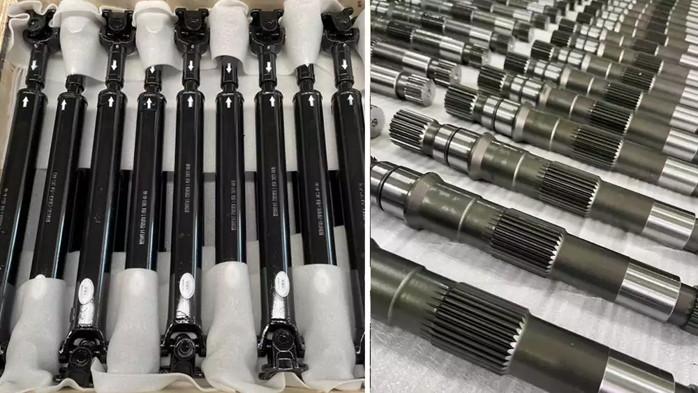
Custom driveshaft manufacturing includes CNC turning, spline machining, heat treatment, finishing, and dynamic balancing. Strict inspection of runout, straightness, and hardness ensures the shaft meets design intent.
The machining stage often follows best practices used in CNC machining of shafts, where concentricity and surface finish directly affect balance and bearing life.
CNC Machining and Splines
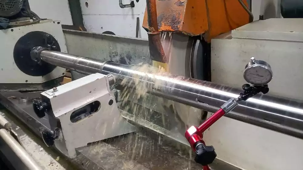
I rough turn first, then finish turn between centers. This keeps concentricity tight. Splines are cut by hobbing or milling. Profile accuracy is critical for load sharing.
Heat Treatment
Heat treatment raises strength and wear resistance. I control hardness and distortion. Shafts often need straightening after quench.
Case Study from My Shop
I worked on a custom driveshaft for an electric utility vehicle.
| Item | Value |
|---|---|
| Material | 42CrMo4 (quenched & tempered) |
| Length | 820 mm |
| Outer Diameter | 38 mm |
| Wall Thickness | Solid shaft |
| Peak Torque | 1,200 Nm |
| Max Speed | 4,500 RPM |
| Runout Spec | ≤ 0.03 mm |
| Balance Grade | G6.3 |
We used CNC turning between centers and spline hobbing. After heat treatment to 32–36 HRC, we ground bearing seats. Final dynamic balancing removed 6 grams at two planes. Field vibration dropped by 40% compared to the prototype shaft.
Inspection
I always check:
- Total indicated runout
- Straightness over full length
- Hardness after heat treat
- Spline profile accuracy
- NDT if safety critical
How Should You Choose a Supplier and Prepare an RFQ?
I have been on both sides. I design parts, and I run machines. Clear data saves weeks of emails.
A good driveshaft supplier shows strong engineering support, in-house machining and balancing, and clear quality control. A detailed RFQ with torque, speed, drawings, and quantity ensures an accurate quote.
When I evaluate suppliers, I also look at whether they provide integrated precision CNC shaft solutions instead of only basic turning. Full-process control reduces risk.
What I Look for in a Manufacturer
I check if they machine shafts in-house. I ask about balancing equipment. I ask how they control heat treatment. Experience in automotive or industrial power transmission is a big plus.
RFQ Data Checklist
| Information | Why It Is Needed |
|---|---|
| Application Description | Understand duty and risk |
| Max & Continuous Torque | Size and material choice |
| Speed Range | Critical speed check |
| Drawings or 3D Model | Machining accuracy |
| Tolerance & Runout | Process planning |
| Surface Treatment | Corrosion and wear |
| Annual Volume | Process and pricing |
When I send all this at the start, quotes come back faster and with fewer surprises.
Conclusion
A reliable custom driveshaft comes from clear requirements, smart material choice, controlled manufacturing, and close work with the right supplier.

-
Explore this link to understand how Peak Torque determines the minimum shaft diameter, crucial for reliable mechanical design. ↩
-
Learn why maintaining operating speed below Critical Speed prevents excessive vibration and premature bearing failure. ↩
-
Explore this link to understand why 4140 and 4340 steels are preferred for high torque due to their strength and heat treatment response. ↩
