Last updated on April 28, 2026, by Lucy
In precision machining, surface roughness can quietly ruin performance or inflate costs. Many engineers either overlook it or over-specify it without realizing the trade-offs.
Surface roughness is the measurable texture of a machined surface, typically expressed as Ra or Rz, and it directly impacts friction, sealing, fatigue life, and manufacturing cost. The right choice is not the smoothest finish, but the one that meets functional needs at the lowest cost.
I have seen projects fail not because of poor design, but because of incorrect surface finish assumptions. So I will break this down in a practical way that you can apply directly.
What Is Surface Roughness & Why Does It Matter in Engineering?
Surface roughness often gets confused with overall finish. This leads to wrong specs and unnecessary cost increases.
Surface roughness measures microscopic peaks and valleys on a surface, while surface finish includes roughness, waviness, and texture; engineers rely on roughness values like Ra to control performance-critical features.
If you misunderstand this concept, you will either overspend or risk failure. So it is worth getting it right from the start.
Surface Roughness vs Surface Finish
Many engineers mix these two terms. I did the same early in my career.
- Surface roughness → micro-level irregularities
- Surface finish → full surface condition including lay and waviness
This matters when you read drawings or define specs for suppliers. In practice, understanding the distinction becomes easier when comparing real-world applications like this detailed surface finish and roughness comparison guide, where both concepts are applied side by side.
Key Surface Roughness Parameters
| Parameter | Meaning | Use Case |
|---|---|---|
| Ra | Average roughness | General-purpose specification |
| Rz | Peak-to-valley average | Sealing and wear surfaces |
| Rt | Total height | High-precision requirements |
Ra is common, but it hides extremes. Rz gives better insight when peaks matter.1
Why Surface Roughness Matters
Surface roughness directly affects2:
- Friction and wear behavior
- Sealing capability
- Fatigue strength
- Visual and tactile quality
I once reduced Ra from 3.2 µm to 1.6 µm on a rotating part. Fatigue life improved noticeably, and failure rates dropped.
Surface Roughness Measurement Methods & Standards?
Many teams specify roughness, but fewer truly verify it correctly.
Surface roughness is measured using contact tools like stylus profilometers or non-contact methods like optical scanners, and standards such as ISO and ASME define how values are measured and specified.

If your measurement method is wrong, your data is meaningless. So this step is critical.
Contact Measurement Methods
Stylus profilometers are the industry standard.
- A diamond tip traces the surface
- It records vertical deviations
- Outputs include Ra and Rz
They are accurate and widely accepted, but not ideal for soft materials.
Non-Contact Measurement Methods
These methods are gaining popularity:
- Optical systems
- Laser scanning
They are ideal for fragile or complex surfaces and provide full 3D mapping.
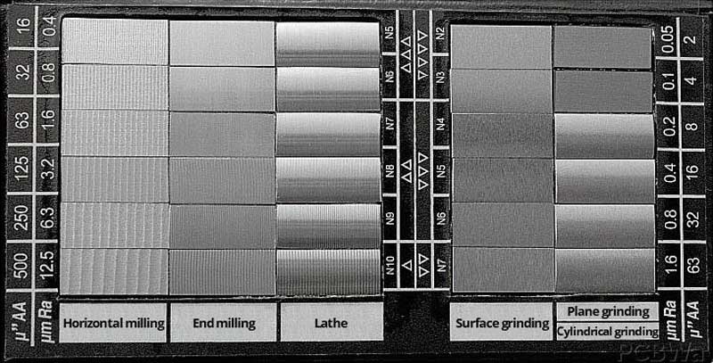
Comparison Methods
Surface roughness comparators are quick tools:
- Based on standard samples
- Used by touch or visual comparison
They are useful on the shop floor, but not for precision validation.
Surface Roughness Standards
Standards align expectations globally.
- ISO standards dominate in Europe3
- ASME standards are common in the US
For EU clients, ISO 1302 is essential for drawing interpretation.
What Affects Surface Roughness in CNC Machining?
Surface roughness is not random. It is controlled by process variables.
Surface roughness in CNC machining is mainly affected by feed rate, cutting speed, tool condition, material type, machine stability, and cooling; among these, feed rate and tool wear usually have the largest impact.
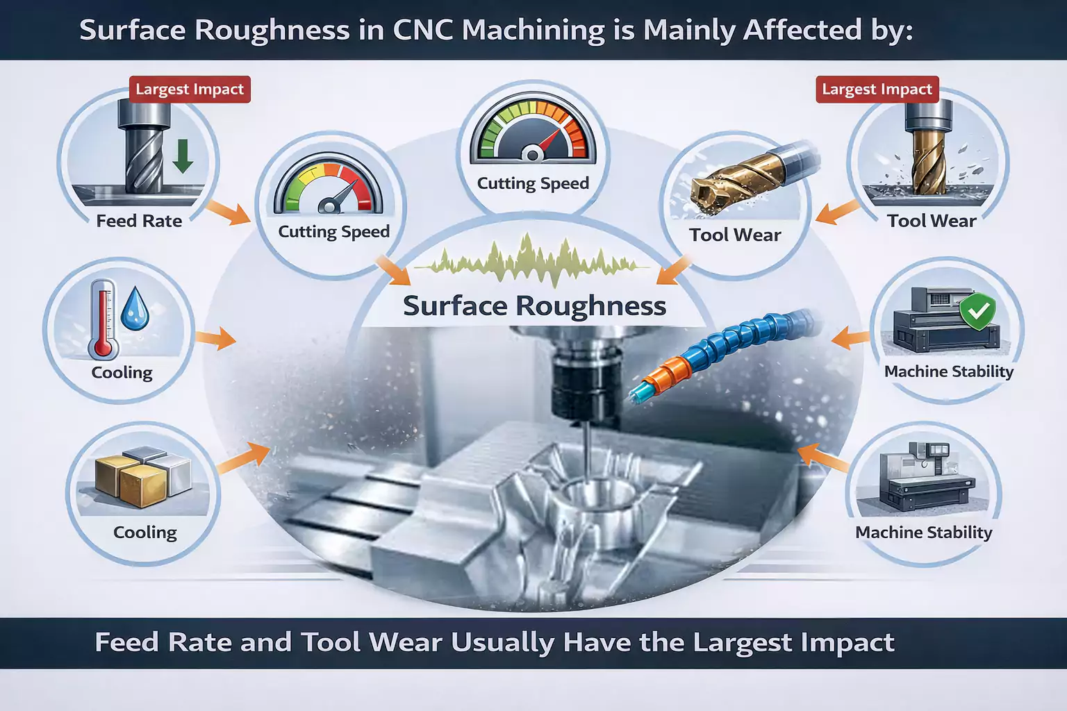
If you control these factors, you control the outcome. If not, variation will creep in.
Machining Parameters
| Parameter | Effect |
|---|---|
| Cutting Speed | Higher speed often improves finish |
| Feed Rate | Higher feed increases roughness |
| Depth of Cut | Larger depth can worsen finish |
Feed rate is usually the most sensitive variable.
Tooling Factors
- Tool geometry affects chip flow
- Tool wear increases roughness significantly
I have seen roughness double simply because the tool was not replaced in time.
Material Properties
Material behavior matters:
- Aluminum → easier to achieve smooth finish
- Stainless steel → risk of built-up edge
- Titanium → tearing and poor finish
Each material needs its own strategy.
Machine & Setup Conditions
- High rigidity improves stability
- Poor fixturing leads to chatter
Chatter marks are one of the most common surface defects.4
Coolant & Lubrication Effects
- Dry cutting increases roughness
- Proper coolant improves finish and tool life
Case Study: Improving Surface Finish in CNC Milling
I worked on a precision housing with a requirement of Ra ≤ 1.6 µm. The first result failed.
| Parameter | Before | After |
|---|---|---|
| Cutting Speed | 120 m/min | 180 m/min |
| Feed Rate | 0.20 mm/rev | 0.10 mm/rev |
| Tool Condition | Worn | New |
| Coolant | Minimal | Optimized |
| Resulting Ra | 3.2 µm | 1.4 µm |
The improvement was not from one change. It was from controlling the full system.
This is where many teams go wrong. They adjust one variable and expect results. Real improvement requires a combined approach.
Surface Roughness Requirements & How to Choose the Right Finish?
This is where engineering decisions directly affect cost.
The correct surface roughness is the lowest value that satisfies functional requirements, because every reduction in Ra significantly increases machining time, tooling cost, and overall production expense.
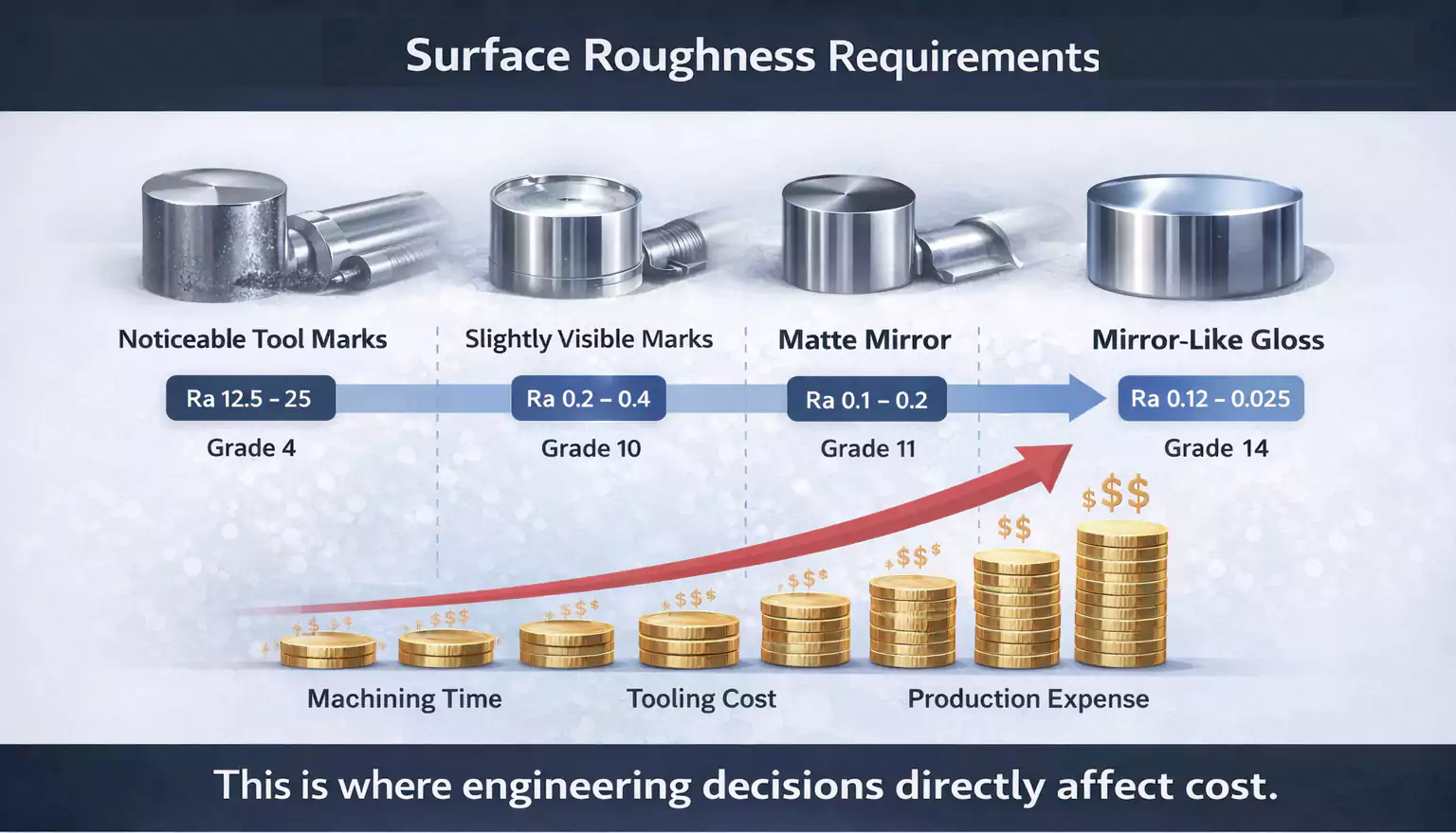
Many engineers aim for perfection. But in manufacturing, perfection is expensive and often unnecessary.
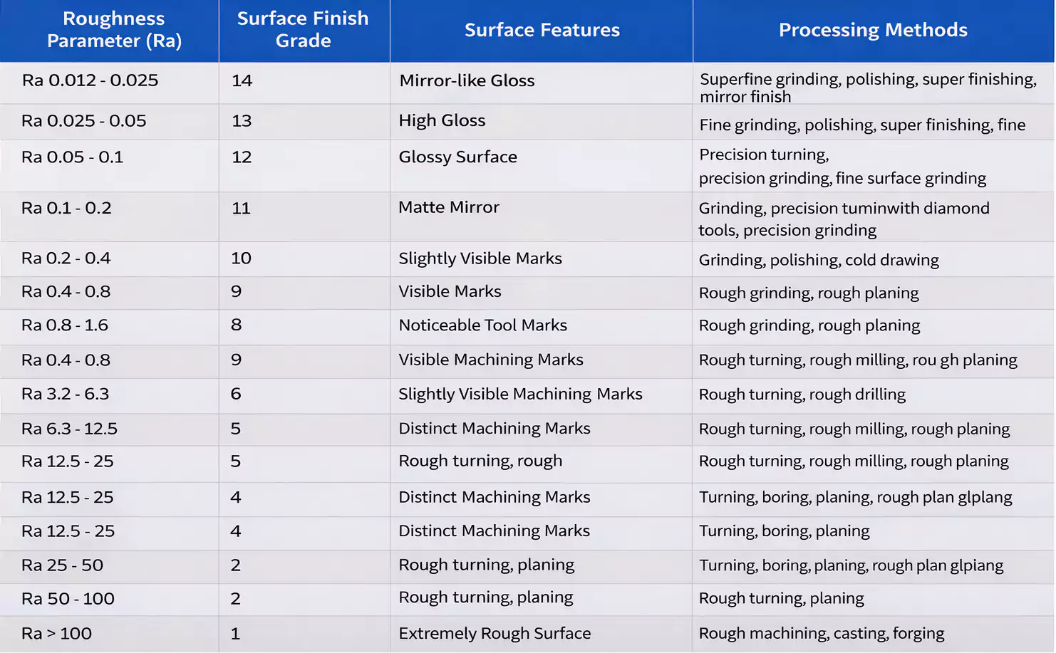
Typical Surface Roughness Values by Process
| Process | Typical Ra (µm) |
|---|---|
| CNC Milling | 0.8 – 3.2 |
| CNC Turning | 0.8 – 1.6 |
| Grinding | 0.2 – 0.8 |
| Polishing | 0.05 – 0.2 |
Lower values require slower speeds, better tools, and extra processes. In many real applications, these finishes are further enhanced through advanced surface finishes in CNC machining capabilities, depending on functional needs.
Surface Roughness Symbols in Engineering Drawings
- Basic symbol defines requirement
- Values specify Ra
- Additional marks indicate process constraints
Basic Symbols
Standard surface finish symbol, applicable to surfaces produced by any method.
Material removal by machining
The horizontal bar shows machining is needed, with extra material added.
Material Removal Prohibited
Indicates the surface must be formed by processes like casting or forging, with no material removal.
Surface Finish Parameters

a – average roughness value (Ra);
b – production method, coating, note, or other additional information;
c – roughness sampling length in millimeters or inches;
d – direction of the surface lay;
e – minimum material removal requirement in millimeters;
f – alternate surface finish parameter.
Common Codes:
Ra = average roughness
Rz = ten-point height roughness
Ry = maximum height roughness
RMS = Root Mean Square
CLA = Centerline Average Roughness
Rt = Total height roughness
N = Grade value
Clear drawings reduce miscommunication.
How to Choose the Right Surface Roughness
I use three simple checks.
Functional Requirements
- Sealing → low roughness
- Sliding → controlled roughness
- Structural → higher roughness acceptable
Cost vs Performance
Each improvement step costs more.
Avoid Over-Specification
This is the most common issue I see.
I often review drawings where Ra 0.4 µm is specified unnecessarily. In many cases, Ra 1.6 µm works perfectly.
Post-Processing & Surface Finishing Options
- Anodizing for corrosion resistance
- Polishing for smoother surfaces
- Electroplating for functional coatings
These finishing choices are often part of broader strategies such as surface treatment in CNC machining processes, where both protection and performance are considered together. In addition, understanding different common surface treatment processes helps in selecting the most cost-effective method without overengineering the part.
These should be planned early, not added as a fix.
Conclusion
Surface roughness is not about chasing the lowest number. It is about making informed engineering decisions. When you align roughness with function, apply the right machining strategy, and use suitable surface treatments, you control cost, improve durability, and build products that perform exactly as intended.

-
"Surface roughness - Wikipedia", https://en.wikipedia.org/wiki/Surface_roughness. Technical standards and surface metrology literature explain that Ra (average roughness) does not account for extreme peaks or valleys, whereas Rz (average peak-to-valley height) provides more information about surface extremes, which is critical for certain applications. Evidence role: definition; source type: education. Supports: Ra is common, but it hides extremes. Rz gives better insight when peaks matter.. Scope note: The practical relevance of Ra versus Rz depends on the specific engineering requirements and surface function. ↩
-
"Surface roughness effect on fatigue strength of aluminum alloy ...", https://pmc.ncbi.nlm.nih.gov/articles/PMC8481500/. Scholarly sources and engineering handbooks confirm that surface roughness can influence friction, wear, sealing capability, fatigue strength, and the visual or tactile quality of components, though the degree of impact depends on material and application context. Evidence role: expert_consensus; source type: education. Supports: Surface roughness directly affects: - Friction and wear behavior - Sealing capability - Fatigue strength - Visual and tactile quality. Scope note: The influence of surface roughness varies with material, environment, and specific engineering application. ↩
-
"[PDF] INTERNATIONAL STANDARD ISO 21920-1", https://cdn.standards.iteh.ai/samples/72196/5012ce84af1a4629a79764a48401a1db/ISO-21920-1-2021.pdf. European manufacturing and engineering sectors predominantly use ISO standards for surface roughness measurement, as documented in international standards organizations and technical guidelines. Evidence role: general_support; source type: institution. Supports: ISO standards dominate in Europe. Scope note: While ISO standards are dominant, some industries or countries may use additional or alternative standards. ↩
-
"Chatter Marks — What They Are and How to Avoid Them - gtispindle.com", https://gtispindle.com/blog/chatter-marks-what-they-are-and-how-to-avoid-them/. Chatter is widely recognized in manufacturing literature as a frequent cause of surface defects in machining operations, particularly in milling and turning. Evidence role: expert_consensus; source type: institution. Supports: Chatter marks are one of the most common surface defects.. Scope note: The prevalence of chatter marks may depend on machine setup and operational conditions. ↩
