Editor’s Note (Updated October 2025):
We’ve added a case study to this article to help readers better understand how cutting feed and speed optimization directly influences the precision, efficiency, and cost-effectiveness of custom parts manufacturing.Catalogs Hide
If your parts come out dull, your tools don’t last, or your cycle times drag on forever—you’re probably not running the right speeds and feeds. It’s one of those fundamentals every machinist learns the hard way.
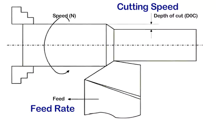
Cutting speed is how fast the tool's cutting edge moves across the material. Feed rate is how quickly the tool advances. Optimizing both is vital for efficient machining, good finish, and tool longevity.

When I first got into CNC machining — and even now, after years of running my own shop — one lesson I still pass down to every new machinist is this: speeds and feeds are everything. They’re not just numbers you punch into the control panel; they’re the heartbeat of the whole cutting process.
From my experience, cutting speed and feed rate come down to how fast the tool moves and how hard it’s working. For engineers who design parts and think about manufacturability, getting these settings right makes all the difference. Nail your feeds and speeds, and you’ll get smooth cuts, long tool life, and consistent parts. Get them wrong, and you’ll end up with broken tools, scrap parts, and wasted hours.
So let’s break down what these two parameters really mean—and why every machinist should master them.
What Exactly Are Cutting Feed and Cutting Speed in Machining?
You hear machinists talk about "speeds and feeds" constantly. But what do these terms really mean, and why are they so foundational to any cutting operation?
Cutting speed refers to the relative surface speed between the cutting tool and workpiece. Feed rate is the speed at which the cutting tool advances along its path.
Diving Deeper into the Definitions
In any machining operation, whether it's milling, turning, or drilling, two primary parameters dictate how the cutting tool interacts with the workpiece material: cutting speed and feed rate. Understanding these is the first step to good machining practice.
-
Cutting Speed (Vc):
- This is the speed at which the cutting edge of the tool moves relative to the surface of the workpiece as it's cutting. Think of it as how fast the material is passing over the tool's edge (or vice-versa).
- It's usually expressed in surface feet per minute1 (SFM) in the imperial system, or meters per minute (m/min) in the metric system.
- For rotating tools like end mills or drill bits, the cutting speed is highest at the outermost diameter of the tool. It's directly related to the machine's spindle speed (RPM) and the tool's diameter.
- The right cutting speed is crucial for achieving proper chip formation2, managing heat at the cutting zone, and ensuring good tool life. Too high, and you can burn up your tool; too low, and you might get built-up edge or poor surface finish.
-
Feed Rate (F):
- This is the rate at which the cutting tool is advanced along its cutting path into or across the workpiece.
- It can be expressed in several ways:
- Feed per minute (e.g., inches per minute or IPM / mm per minute): This is the linear travel speed of the tool or workpiece. This is what you typically program into a CNC machine for milling.
- Feed per revolution (IPR / mm/rev): Common in turning and drilling, it's how much the tool advances for each full rotation of the workpiece or tool.
- Feed per tooth (FPT or chip load - IPT / mm/tooth): For multi-toothed cutters like end mills, this is the amount of material each cutting edge (tooth) removes per revolution. This is a very important parameter for calculating the feed per minute.
From my own time on the shop floor, I’ve learned that smooth cuts and long tool life all come down to balance—how fast the tool spins and how fast it feeds into the material. Get that relationship right, and the cut just flows. Get it wrong, and you’ll fight chatter, wear, and wasted time every single run.
What Does 'Cutting Speed' Truly Mean for Your Machining Process?
We defined cutting speed, but what does that value—like SFM or m/min—actually tell you? How does it translate from a number on a chart to real-world cutting action?
Cutting speed (surface speed) is the velocity of the tool's cutting edge relative to the workpiece material. It directly impacts heat generation, tool wear, and the material removal rate.
Diving Deeper into the Significance of Cutting Speed
Cutting speed, often denoted as $V_c$, is more than just how fast the spindle (RPM) is turning. It's the actual speed that the cutting edges of your tool see as they slice through the material. For engineers like David, understanding this helps in appreciating why certain RPMs are chosen for different tools and materials.
Relationship to RPM:
For a rotating tool (like an end mill or drill bit) or a rotating workpiece (like in turning), the cutting speed ($V_c$) is directly proportional to the spindle speed (N, in revolutions per minute or RPM) and the diameter (D) of the tool or workpiece.
The formulas are:
- Imperial: $V_c \text{ (SFM)} = \frac{\pi \times D \text{ (inches)} \times N \text{ (RPM)}}{12}$
- Metric: $V_c \text{ (m/min)} = \frac{\pi \times D \text{ (mm)} \times N \text{ (RPM)}}{1000}$
This means for a given material (which has a recommended cutting speed), a smaller diameter tool will need to spin at a higher RPM to achieve that same surface speed compared to a larger diameter tool.
Impact on Machining:
- Heat Generation: The cutting speed is a primary factor in how much heat is generated at the cutting zone. Higher cutting speeds generally mean more heat. If the heat isn't managed (e.g., through coolant or the tool's ability to withstand it), it can lead to premature tool wear, tool failure, or damage to the workpiece.
- Tool Wear: Every cutting tool material (HSS, carbide, ceramic) has an optimal cutting speed range for a given workpiece material. Exceeding this can rapidly accelerate wear mechanisms like abrasion, adhesion, or diffusion.
- Chip Formation3: Cutting speed influences how chips are formed. Too low a speed can sometimes lead to a "built-up edge" (BUE), where workpiece material welds to the tool tip, degrading surface finish and tool life.
- Surface Finish: While feed rate often has a more direct impact, cutting speed also plays a role. An appropriate cutting speed helps achieve a cleaner shear.
- Material Removal Rate (MRR): While primarily driven by feed rate and depth of cut, operating at the highest permissible cutting speed (that still ensures good tool life) contributes to maximizing MRR.
Getting the cutting speed right is a fundamental aspect of optimizing any machining operation, directly impacting the points in my insight about smoother cuts and tool longevity.
What Factors Should You Consider When Setting Cutting Speed in CNC Machining?
Choosing the right cutting speed isn't a wild guess. What key elements must an engineer or machinist evaluate to determine the optimal surface speed for a CNC job?
Consider workpiece material hardness and type, cutting tool material (HSS, carbide), type of operation (roughing/finishing), machine rigidity and power, and the use of coolant.

Diving Deeper into Factors Guiding Cutting Speed Selection
Setting the correct cutting speed is crucial for successful CNC machining, and it's influenced by a combination of factors. When I'm programming a job or advising an engineer like David, these are the main things we consider:
-
Workpiece Material:
- Hardness and Strength: Harder and stronger materials (like alloy steels, stainless steels, or exotic alloys) generally require lower cutting speeds compared to softer materials (like aluminum or mild steel).
- Abrasiveness: Some materials (like cast iron or certain composites) are abrasive and can wear tools quickly, often necessitating lower cutting speeds or more wear-resistant tool coatings.
- Thermal Conductivity: Materials that are poor thermal conductors (like titanium or stainless steel) tend to concentrate heat in the cutting zone, requiring lower speeds to prevent overheating the tool.
-
Cutting Tool Material:
- High-Speed Steel (HSS): Has lower hot hardness, so it requires significantly lower cutting speeds than carbide.
- Cobalt HSS (HSS-Co): Can handle slightly higher speeds than standard HSS due to better heat resistance.
- Solid Carbide4: Has excellent hot hardness and wear resistance, allowing for much higher cutting speeds, often 3 to 5 times (or more) than HSS for the same material.
- Ceramics and CBN/PCD: These advanced materials can operate at even higher cutting speeds but are typically used for specific applications (e.g., ceramics for hard turning, PCD for non-ferrous).
-
Type of Operation:
- Roughing: The primary goal is high material removal rate. Cutting speeds might be slightly reduced from optimum to prioritize tool life with heavier depths of cut and feeds.
- Finishing: The goal is good surface finish and dimensional accuracy. Cutting speeds are often optimized for the best finish, sometimes slightly higher than roughing speeds if chip load is light.
-
Machine Tool Rigidity, Spindle Power, and Condition:
- A rigid, powerful machine in good condition can handle higher cutting speeds and forces without excessive vibration or chatter, which can damage the tool or workpiece. Older or less rigid machines might require more conservative parameters.
-
Coolant (Cutting Fluid) Usage:
- Proper application of coolant can effectively remove heat from the cutting zone, flush away chips, and provide lubrication. This often allows for higher cutting speeds and extends tool life. Some operations or material/tool combinations are run dry, but the cutting speed must be adjusted accordingly.
Balancing these factors is key to finding that sweet spot for cutting speed that ensures efficiency, quality, and good tool economy.
Cutting Feed Rate vs. Surface Speed: What's the Key Difference?
"Feed rate" and "surface speed" are both about motion in machining, but they're not the same. How do these two critical parameters differ, and why does it matter?
Surface speed (cutting speed) is how fast the tool edge cuts the material (e.g., SFM). Feed rate is how fast the tool advances along its path (e.g., IPM or feed per tooth).

Diving Deeper into Distinguishing Feed and Speed
It's really important for anyone involved in machining, from an operator to an engineer like David, to clearly understand the difference between cutting speed (often called surface speed) and feed rate. While they both relate to how "fast" things are happening, they describe different aspects of the cutting process.
Cutting Speed (Vc or Surface Speed):
- What it is: As we've discussed, this is the speed of the tool's cutting edge relative to the workpiece surface. For a rotating tool, it depends on the RPM and the tool's diameter.
- Units: Surface Feet per Minute (SFM) or meters per minute (m/min).
- What it primarily affects: Heat generation at the cutting edge, tool life (due to temperature-related wear), and to some extent, chip formation.
- How it's set (indirectly): You typically look up a recommended cutting speed for your tool/material combination and then calculate the required spindle RPM based on your tool diameter using the formulas:
- $RPM = \frac{V_c \text{ (SFM)} \times 12}{\pi \times D \text{ (inches)}}$
- $RPM = \frac{V_c \text{ (m/min)} \times 1000}{\pi \times D \text{ (mm)}}$
Feed Rate (F):
- What it is: This is the rate at which the tool advances into or along the workpiece. It dictates how much material each cutting edge removes.
- Units:
- Inches Per Minute (IPM) or mm/minute: This is the linear speed of the machine table or tool axis. This is typically what's programmed in a CNC mill's G-code (e.g., F20.0 for 20 IPM).
- Inches Per Revolution (IPR) or mm/revolution: Often used in turning or drilling.
- Inches Per Tooth (IPT) or mm/tooth (also known as chip load, $f_z$): This is the thickness of material removed by each tooth of a multi-fluted cutter (like an end mill) as it rotates. This is a fundamental parameter.
- What it primarily affects: Chip thickness, surface finish (scallop height), material removal rate, and mechanical load on the tool and machine.
- How it's set (often calculated from chip load): For milling, you often start with a recommended chip load ($f_z$) for your tool/material, then calculate the feed per minute:
- $F \text{ (IPM)} = f_z \text{ (IPT)} \times \text{Number of Teeth (Z)} \times N \text{ (RPM)}$
What I’ve learned over the years is this — you can’t just crank up both feed and speed and hope for the best. They might look like simple numbers, but each one controls a different part of the cut. The trick is finding the sweet spot where they work together. That balance is what gives you smoother cuts, longer tool life, and parts that come off the machine just right.
How Do You Determine the Recommended Cutting Speed for a Job?
Charts and handbooks offer cutting speed data, but how do you find the right recommendation? Is there a magic number, or is it more nuanced than that?
Recommended cutting speeds are typically found in tooling manufacturers' catalogs or machining data handbooks. They are starting points, influenced by material, tool, and operation, requiring adjustments based on results.

Diving Deeper into Finding Starting Points for Cutting Speed
There's no single "magic number" for cutting speed that works for all situations. "Recommended" cutting speeds are essentially well-tested starting points provided by tooling manufacturers and compiled in machining data resources. For an engineer like David looking for guidance, these are invaluable.
Here’s how you typically find and use these recommendations:
-
Tooling Manufacturer's Catalogs and Websites:
- This is often the best place to start. Companies that make cutting tools (end mills, drills, inserts, etc.) invest heavily in testing their products on various workpiece materials. Their catalogs or online resources will provide tables with recommended cutting speeds (SFM or m/min) and often chip loads (IPT or mm/tooth) for specific tool series cutting specific materials.
- These recommendations are usually tailored to their tool's geometry, substrate (e.g., specific carbide grade), and coating.
-
Machining Data Handbooks:
- Comprehensive resources like the "Machinery's Handbook" or specialized "speeds and feeds" guides compile data from various sources. They provide general recommendations for different material groups and tool types.
-
CAM Software Libraries:
- Many Computer-Aided Manufacturing (CAM) software packages have built-in tooling libraries that include recommended cutting speeds and feeds for common materials. These can be customized and expanded.
Using the Recommendations as Starting Points:
It's crucial to remember that these are starting points. The "recommended" values usually assume ideal conditions (good machine rigidity, proper coolant, sharp tool). You'll almost always need to make adjustments based on your specific setup and the results you observe.
- Start Conservatively: If unsure, it's often wise to start at the lower end of the recommended speed range and perhaps 75-80% of the recommended feed.
- Observe and Adjust: Pay close attention to:
- Chip Formation: Are the chips well-formed, or are they discolored (too hot), powdery (rubbing), or stringy?
- Sound of the Cut: A smooth, consistent sound is good. Screeching, chattering, or hammering indicates a problem.
- Surface Finish: Is it meeting requirements?
- Tool Wear: Monitor how quickly the tool is wearing.
- Machine Load Meter: Keep an eye on spindle and axis loads.
From my years behind the machine at Allied Metal, I’ve found that charts and book values will only get you close. The real skill comes from experience — being able to “read the cut” by sight, sound, and feel, and then fine-tuning your speeds and feeds until everything runs just right.
How Do Chip Thinning and Optimum Feed Rate Affect Your Machining?
You've set your speeds and feeds, but sometimes chips look too thin, or tools wear fast. Could "chip thinning" be the issue, and how does it relate to feed rate?
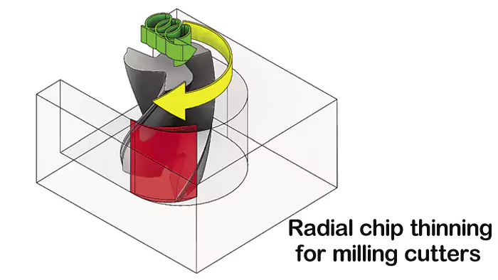
Chip thinning occurs when the radial depth of cut is small, reducing actual chip thickness. You must increase feed rate to compensate and maintain desired chip load, preventing rubbing and improving tool life.
Diving Deeper into Chip Thinning and Feed Optimization
Chip thinning is a phenomenon that often catches machinists by surprise if they aren't aware of it. It particularly comes into play during milling operations when the radial depth of cut (width of cut, or $a_e$) is less than half the cutter's diameter. It also occurs with ball-nose end mills when cutting near the tool's center. Understanding this is crucial for optimizing feed rates, which is precisely the efficiency factor that engineers value.
What is Chip Thinning?
When an end mill takes a cut, the programmed feed per tooth (chip load, $f_z$) assumes that the tool is fully engaged radially, or cutting with its full diameter. However, in many finishing or light roughing passes, the radial engagement is much smaller.
- In this scenario, the actual thickness of the chip being formed is less than the programmed feed per tooth. This is because the cutting edge enters and exits the material at an angle, and the effective cutting diameter is reduced. This effect is known as radial chip thinning.
- A similar effect, axial chip thinning, occurs with ball-nose end mills when the depth of cut is shallow relative to the ball radius, or when profiling curved surfaces.
Why Does It Matter?
If you don't account for chip thinning, your actual chip thickness will be too small.
- Rubbing Instead of Cutting: If the chip is too thin, the cutting edge might rub against the material rather than shearing it cleanly. This generates excess heat, causes rapid tool wear (especially flank wear), can lead to work hardening of the material, and results in a poor surface finish.
- Reduced Productivity: If you're not taking a thick enough chip, your material removal rate is lower than it could be.
Compensating for Chip Thinning (Optimum Feed Rate):
To maintain the desired effective chip thickness and achieve optimal cutting conditions, you need to increase your programmed feed rate when radial chip thinning is significant.
- Tooling manufacturers often provide formulas or "chip thinning factors" to calculate the adjusted feed rate. This adjusted feed rate ensures that even with a small radial engagement, each tooth is taking a healthy bite out of the material.
- This is counterintuitive for some – taking a lighter radial cut often means you can and should feed faster.
What years of cutting metal have taught me is that chip control can make or break a job. You can have perfect speeds and feeds on paper, but if the chip load isn’t right, the tool will tell you—fast. It’s one of those small details that separates smooth, efficient machining from constant frustration. Getting that balance right isn’t theory—it’s something you learn by feel, one cut at a time.
Case Study: Optimizing Feed and Speed for a Precision Aluminum Bracket
One of our long-term clients—a procurement manager from an industrial automation company—requested a batch of precision aluminum brackets used for a robotic assembly line.
Each part required ±0.01 mm tolerance, a Ra 0.8 µm surface finish, and consistent flatness across multiple faces.
Part specifications:
- Material: 6061-T6 Aluminum
- Part dimensions: 120 mm × 80 mm × 12 mm
- Feature highlights: 6 through holes Ø8.00 mm ±0.02; two precision-milled pockets 1.5 mm deep; one side with M6 × 1.0 threaded holes
- Batch quantity: 500 pcs
- Machine used: 3-axis CNC vertical mill (BT40 spindle, 12,000 RPM)
Initial challenge:
The first trial run used a conservative setup — cutting speed Vc = 200 m/min, feed per tooth fz = 0.05 mm/tooth, 4-flute carbide end mill Ø10 mm.
While surface finish met the requirement, the cycle time was 18 minutes per part, which was too long for mass production.
Optimization process:
After adjusting both feed and speed parameters based on tool manufacturer data and actual chip formation:
- New cutting speed: 340 m/min
- Feed per tooth: 0.08 mm/tooth
- Spindle speed: 10,800 RPM
- Feed rate: 3,456 mm/min
- Depth of cut (ap): 2 mm
- Width of cut (ae): 5 mm
Result:
- Cycle time reduced from 18 min → 11.5 min per part
- Tool life extended by 32%
- Surface finish improved from Ra 0.85 → Ra 0.75 µm
- Dimensional repeatability improved due to better chip evacuation and thermal stability
Key takeaway:
By fine-tuning cutting speed and feed rate—not by large margins, but through controlled, data-driven adjustments—the production manager achieved faster throughput without sacrificing precision or surface quality.
This illustrates how even small optimizations in “feeds and speeds” can translate into major gains in CNC part manufacturing efficiency.
Conclusion
Optimizing cutting speed and feed rate is essential for efficient machining, superior surface finish, and extended tool life. Understanding these parameters leads to better parts and productivity.

-
Surface feet per minute is a key measurement in machining. Learn more about its significance and applications in this resource. ↩
-
Chip formation is critical for machining efficiency. Discover how it impacts tool life and surface finish by exploring this topic further. ↩
-
Understanding Chip Formation is crucial for optimizing machining processes and improving tool life. Explore this link for in-depth insights. ↩
-
Discover why Solid Carbide is favored for its hot hardness and wear resistance, enhancing efficiency in cutting operations. ↩
