G-code can look confusing at first. Many engineers and beginners see endless letters and numbers and feel lost before the machine even starts moving.
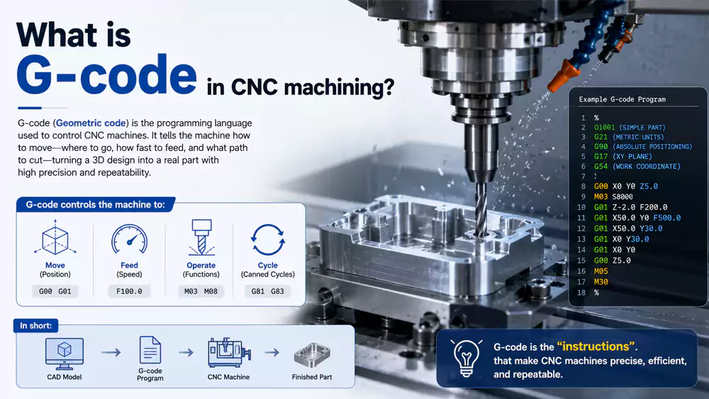
G-code is the programming language used in CNC machining to control movement, speed, tool paths, and machining operations. It converts CAD and CAM data into precise machine actions so CNC machines can produce accurate parts repeatedly and efficiently.

Every CNC machinist remembers the first time they saw a machine follow a program perfectly. I still remember watching a machining center cut aluminum within ±0.01 mm tolerance from a few lines of code. That moment changed how I viewed manufacturing forever. G-code is not just machine language. It is the bridge between a digital drawing and a real precision part. Once you understand the basics, you gain much more control over machining quality, cycle time, and production cost.
What Is G-Code in CNC Machining?
Many new CNC operators think G-code is too technical. They depend fully on CAM software and never learn what the machine is actually doing.
G-code is a standardized CNC programming language that tells a machine how to move, where to cut, how fast to run, and which machining operation to perform during manufacturing.
Why G-Code Matters in Real Manufacturing
I often tell new engineers that G-code is like learning the grammar of machining. CAM software generates programs automatically, but experienced machinists still read and edit code manually every day. Small changes in feed rate, spindle speed, or tool compensation can improve surface finish and reduce machining time.
A typical CNC program controls:
| Function | Example | Purpose |
|---|---|---|
| Rapid movement | G0 | Fast positioning |
| Linear cutting | G1 | Straight cutting motion |
| Circular interpolation | G2/G3 | Arc and radius cutting |
| Tool compensation | G41/G42 | Cutter offset control |
| Coordinate system | G54-G59 | Work offsets |
| Drilling cycles | G81-G89 | Automated hole machining |
Most CNC machines follow either the Fanuc-style format or a similar standard1. Even though brands differ, the core logic stays very close.
How G-Code Connects CAD and Manufacturing
The workflow usually starts with a CAD model. Then CAM software creates toolpaths. After that, the software converts those toolpaths into G-code. Finally, the CNC machine reads the code line by line.
A simple line like this:
G1 X50 Y25 F200means:
- G1 = linear cutting move
- X50 Y25 = target coordinates
- F200 = feed rate
That single line controls real cutting motion on expensive equipment. If the code is wrong, the machine may scrap the part or damage the tool. That is why understanding G-code still matters even in highly automated factories.
Case Study: Reducing Cycle Time with Manual G-Code Optimization
A few years ago, I worked on an aluminum robotics housing project for an automation customer. The CAM-generated program worked, but the cycle time was too long.
After reviewing the code manually, we optimized tool transitions and feed rates2.
| Parameter | Original Program | Optimized Program |
|---|---|---|
| Material | 6061 Aluminum | 6061 Aluminum |
| CNC Machine | VMC-850 | VMC-850 |
| Tool Changes | 11 | 8 |
| Average Feed Rate | 1200 mm/min | 1800 mm/min |
| Cycle Time | 42 min | 31 min |
| Surface Finish | Ra 1.8 | Ra 1.5 |
| Scrap Rate | 4% | 1% |
The customer saved almost 26% machining time per part. That improvement came mainly from understanding the actual G-code instead of relying only on software defaults.
Complete G-Code List (CNC G-Code Chart)
Many CNC beginners search for a complete G-code chart because remembering every command feels overwhelming at first.
A CNC G-code chart lists standard commands used for movement, drilling, compensation, coordinate systems, and machining cycles from G0 to G99.
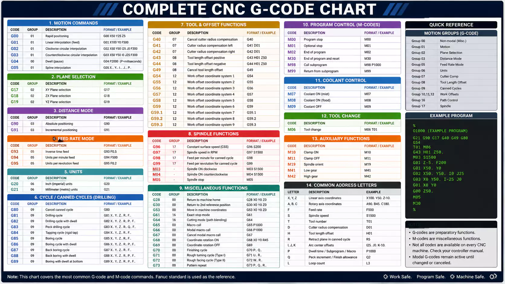
Common CNC G-Codes from G0 to G99
Below is a practical list of commonly used G-codes found on many CNC milling machines and machining centers.
| G-Code | Function | Description |
|---|---|---|
| G0 | Rapid Positioning | Fast non-cutting movement |
| G1 | Linear Interpolation | Straight cutting movement |
| G2 | Circular Interpolation CW | Clockwise arc cutting |
| G3 | Circular Interpolation CCW | Counterclockwise arc cutting |
| G4 | Dwell | Pause operation |
| G17 | XY Plane Selection | Plane selection |
| G18 | ZX Plane Selection | Plane selection |
| G19 | YZ Plane Selection | Plane selection |
| G20 | Inch Mode | Use inches |
| G21 | Metric Mode | Use millimeters |
| G28 | Return to Home | Machine zero return |
| G40 | Cancel Cutter Compensation | Offset cancel |
| G41 | Cutter Compensation Left | Tool radius offset |
| G42 | Cutter Compensation Right | Tool radius offset |
| G43 | Tool Length Compensation | Tool height offset |
| G49 | Cancel Tool Length Offset | Offset cancel |
| G54-G59 | Work Coordinate Systems | Fixture offsets |
| G73 | High-Speed Peck Drilling | Fast chip breaking |
| G81 | Simple Drilling Cycle | Standard drilling |
| G82 | Spot Drilling Cycle | Drilling with dwell |
| G83 | Peck Drilling Cycle | Deep hole drilling |
| G84 | Tapping Cycle | Thread tapping |
| G90 | Absolute Programming | Fixed coordinate reference |
| G91 | Incremental Programming | Relative movement |
| G94 | Feed per Minute | Feed mode |
| G95 | Feed per Revolution | Feed mode |
Which G-Codes Are Used Most Often?
In daily machining work, I see a small group of codes used constantly. Most programs rely heavily on:
- G0
- G1
- G2
- G3
- G54
- G81
- G90
These commands form the foundation of CNC programming. Once beginners understand these codes well, reading CNC programs becomes much easier.
Tips for Learning G-Code Faster
I usually suggest learning G-code in layers instead of memorizing everything at once.
Start with:
- Motion commands
- Coordinate systems
- Tool compensation
- Drilling cycles
- Advanced macros
Reading real programs helps much more than studying charts alone. I learned fastest by standing beside machines and watching each command create actual movement.
Common M-Codes Used with G-Code
Many people focus only on G-codes. Then they become confused when the spindle or coolant does not work correctly.
M-codes are auxiliary machine commands used alongside G-code to control spindle rotation, coolant flow, tool changes, and machine functions.
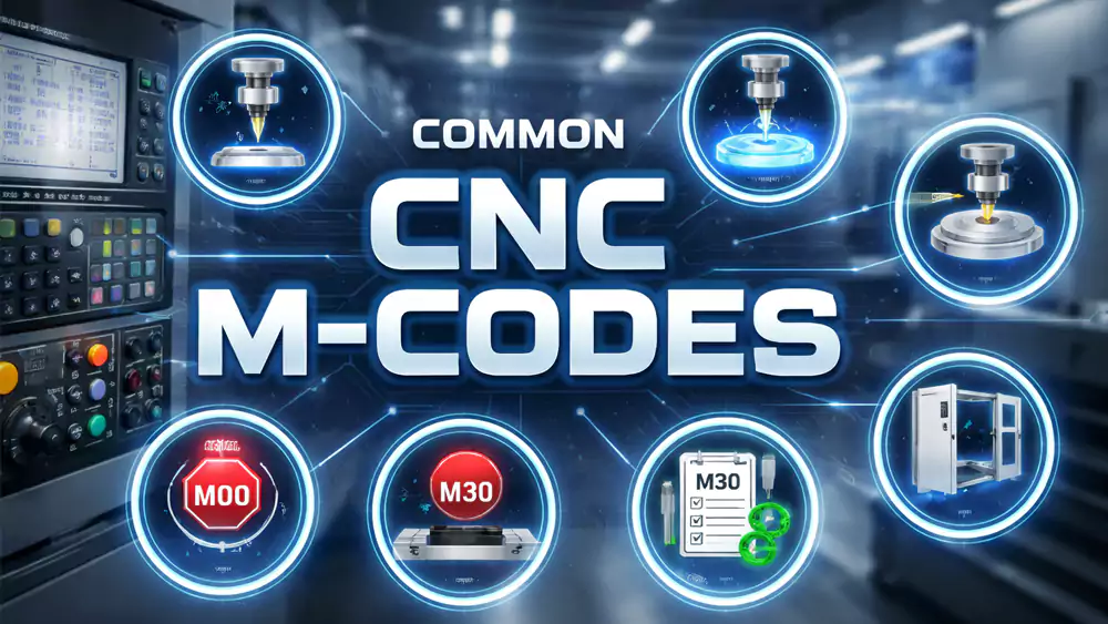
Most Frequently Used M-Codes
M-codes handle machine operations that are not directly related to tool movement.
| M-Code | Function | Description |
|---|---|---|
| M0 | Program Stop | Temporary stop |
| M1 | Optional Stop | Conditional stop |
| M3 | Spindle On CW | Clockwise spindle rotation |
| M4 | Spindle On CCW | Counterclockwise spindle rotation |
| M5 | Spindle Stop | Stop spindle |
| M6 | Tool Change | Automatic tool change |
| M8 | Coolant On | Start coolant |
| M9 | Coolant Off | Stop coolant |
| M30 | End Program | Program reset and end |
Why M-Codes Matter in Production
I once saw a damaged titanium part because coolant activation was missing in the program. The tool overheated and failed during roughing.
The movement commands were correct. The missing M8 command caused the issue.
That experience reminded me that CNC programming is not only about geometry. It also controls heat, chip evacuation, spindle direction, and machine safety.
Combining G-Codes and M-Codes
A normal CNC line may include both:
G1 X100 Y50 F300 M8This line performs cutting movement while turning coolant on at the same time.
That coordination is what makes CNC machining highly automated and repeatable.
Example CNC Program Using Common G-Codes
Many beginners understand theory but struggle when reading a full CNC program for the first time.
A basic CNC program combines G-codes and M-codes to control machine movement, spindle speed, tool changes, drilling cycles, and program completion.
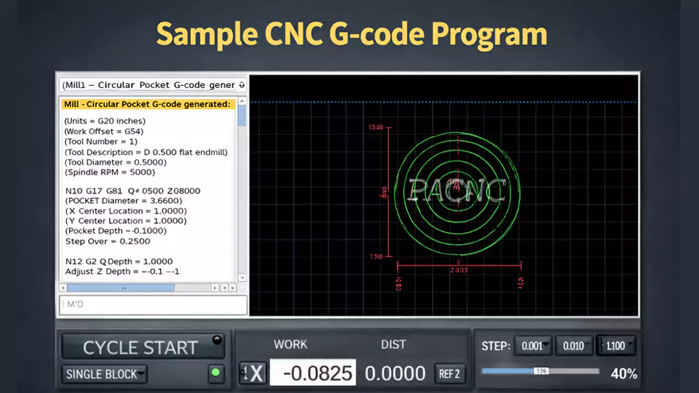
Simple CNC Milling Program Example
Below is a basic example for milling a rectangular pocket in aluminum.
%
O1001
G21
G17 G90 G40 G49 G80
T1 M6
G54
S2500 M3
G0 X0 Y0
G43 H1 Z50
M8

G0 Z5
G1 Z-2 F150
G1 X100 Y0 F300
G1 X100 Y50
G1 X0 Y50
G1 X0 Y0

G0 Z50
M9
M5
G28 G91 Z0
G90
M30
%
Program Breakdown
| Line | Purpose |
|---|---|
| G21 | Metric units |
| G90 | Absolute positioning |
| T1 M6 | Tool change |
| S2500 M3 | Start spindle |
| M8 | Coolant on |
| G1 commands | Cutting movement |
| G28 | Return home |
| M30 | End program |
What Engineers Should Pay Attention To
Experienced engineers usually focus on:
- Safe tool entry
- Proper feed rates
- Chip evacuation
- Machine clearance
- Tool wear compensation
The code may look simple, but every line affects machining quality and efficiency.
I still manually review CNC programs before production runs, especially for expensive materials like Inconel or titanium. Even modern CAM systems can generate inefficient toolpaths if the setup is not optimized correctly.
FAQ
Is G-code difficult to learn?
No. Most beginners can understand basic G-code within a few weeks if they practice reading simple programs daily.
What is the difference between G-code and M-code?
G-codes control movement and machining operations. M-codes control machine functions like spindle rotation, coolant, and tool changes.
Do all CNC machines use the same G-codes?
Most CNC machines use similar standards, especially Fanuc-style programming. Still, some machine brands add custom commands.
Can CAM software replace manual G-code programming?
CAM software creates programs automatically, but understanding G-code helps improve efficiency, troubleshoot errors, and optimize machining quality.
What is the most common G-code?
G0 and G1 are the most commonly used commands because they control rapid movement and linear cutting.
Conclusion
G-code is the foundation of CNC machining. Once you understand the language behind machine movement, you gain much more control over quality, efficiency, and manufacturing success.
Want reliable CNC machining support for prototypes or production parts? At Allied Metal, I work closely with engineers who need tight tolerances, fast lead times, and stable quality. If you need help with CNC machining, rapid prototyping, or production optimization, feel free to reach out and discuss your project with our team.

-
"Discovering Fanuc G Codes and CNC G Code Commands", https://www.mroelectric.com/blog/g-code-cnc/. ISO 6983 and RS274-based descriptions of numerical control programming show that CNC part programs commonly use standardized G- and M-code formats, with controller-specific dialects such as Fanuc-style syntax. Evidence role: historical_context; source type: institution. Supports: Most CNC machines use Fanuc-style G-code formatting or a closely related standardized format.. Scope note: This supports the existence and broad influence of standardized G-code formats, but it may not quantify the share of machines using Fanuc-style controllers specifically. ↩
-
"Model-based feed rate optimization for cycle time reduction in milling", https://www.sciencedirect.com/science/article/abs/pii/S1526612523002487. Research on CNC toolpath and feed-rate optimization reports that adjusting non-cutting movements, transitions, and feed parameters can reduce machining time while maintaining process constraints. Evidence role: mechanism; source type: paper. Supports: Manual optimization of tool transitions and feed rates can reduce CNC cycle time compared with an unoptimized CAM-generated program.. Scope note: This provides contextual support for the mechanism behind cycle-time reduction; it does not independently verify the article’s specific project data or percentage improvement. ↩
