Updated on December 17, 2025 by Lucy
Are you struggling with grooving quality issues in your custom components? This guide reveals professional solutions to common machining challenges.
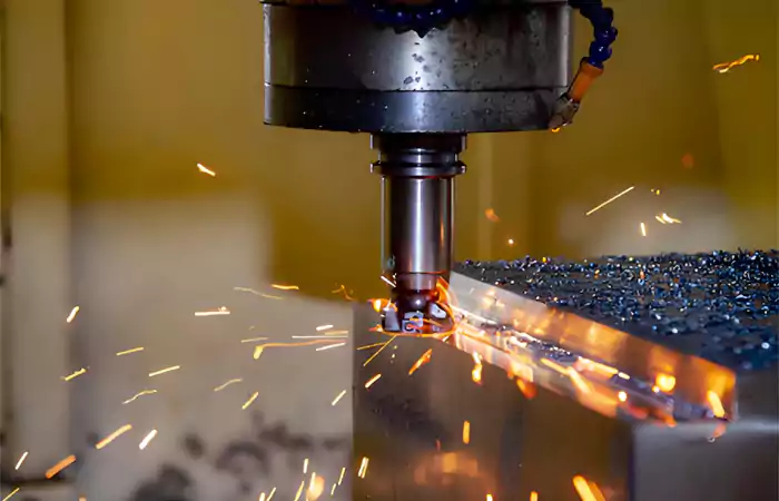
Grooving machining creates precise grooves on components using specialized cutting tools. This process meets strict tolerance requirements for industrial applications.

I remember when I first started in the machining business, I faced a grooving project that almost failed due to poor tool selection. The client needed sealing grooves in hydraulic cylinder components, and we initially used standard tools that couldn't handle the material's hardness. After switching to specialized carbide inserts with proper chipbreakers, we achieved perfect results. That experience taught me the importance of understanding grooving fundamentals.
As someone who started on the shop floor, I've seen how proper grooving techniques can make or break a project. Let me share the insights I've gained from thousands of successful machining jobs.
What Grooving Methods Deliver Optimal Results?
Need to choose the right grooving technique for your project? Understanding different methods ensures better quality and cost efficiency.
Lathe grooving creates external/internal grooves on rotating parts, while milling handles complex contours. Each method serves specific geometrical requirements and production volumes.

Matching Methods to Component Requirements
Your component's geometry dictates the optimal grooving method. Rotational parts like shafts and cylinders benefit from lathe grooving, where the workpiece rotates against a stationary tool. This method excels at creating consistent, concentric grooves for sealing rings or retention features.
For non-rotational parts or complex groove patterns, milling provides superior flexibility. CNC milling machines can produce intricate groove geometries that would be impossible with turning operations. Consider these key factors:
| Factor | Lathe Grooving1 | Milling Grooving |
|---|---|---|
| Suitable Parts | Rotational symmetric | Any shape |
| Groove Complexity | Simple to moderate | High |
| Setup Time | Faster for simple grooves | Longer for complex patterns |
| Cost Efficiency | Better for high-volume round parts | Better for complex, low-volume parts |
Equipment and Tooling Selection
Lathe grooving requires insert-style tools designed for specific groove widths. These tools must withstand continuous cutting forces while maintaining dimensional stability. For milling operations, end mills and specialized slotting cutters provide the necessary cutting geometry.
A recent project for an automotive client demonstrates these principles. They needed piston grooves with ±0.01mm tolerance in 4140 steel.
| Parameter | Value |
|---|---|
| Material | 4140 Steel |
| Groove Width | 3.2mm ±0.01mm |
| Groove Depth | 2.5mm ±0.02mm |
| Surface Finish | Ra 0.8μm |
| Method | CNC Lathe Grooving |
| Tool Used | DNMG insert with chipbreaker |
| Cycle Time | 45 seconds per part |
We achieved these results through careful tool selection and optimized cutting parameters. The right combination delivered the required precision while maintaining production efficiency.
Different types of grooving machining
| Grooving Type | Description | Applications |
|---|---|---|
| Straight Turning | Basic CNC lathe cutting for straight grooves2 | Shafts, rods, cylindrical parts |
| End Face Grooving | Cutting grooves on workpiece end faces | Seals, O-rings, flat surfaces |
| Contour Grooving | CNC-programmed cutting along curves or contours | Automotive, aerospace specialized parts |
| Bore Grooving | Slotting inside workpiece inner holes | Pipes, hydraulic cylinders, internal grooves |
| Multiple Grooving | Creating multiple parallel/staggered grooves | Complex parts requiring multiple functional grooves |
| Cylindrical Grooving | Machining grooves on outer surfaces | Annular grooves, circlips, sealing rings |
How Does Material Selection Impact Grooving Performance?
Wondering why some materials groove beautifully while others cause endless problems? Material properties directly determine your grooving strategy and outcomes.
Softer materials like aluminum allow faster speeds, while hardened steels require specialized tools. Material hardness and machinability guide parameter selection.

Material-Specific Machining Strategies
Each material family demands unique approaches. Aluminum and its alloys, for instance, permit high cutting speeds up to 300-500 meters per minute. However, these materials tend to generate built-up edge on cutting tools, requiring positive rake angles and sharp cutting edges.
Stainless steels present different challenges. Their work-hardening characteristics and low thermal conductivity necessitate moderate speeds and consistent feed rates. Interrupted cuts in stainless steel particularly challenge tool geometry and require robust insert grades.
Consider these material-specific guidelines:
| Material Type | Cutting Speed | Key Considerations |
|---|---|---|
| Aluminum Alloys | 300-500 m/min | Prevent built-up edge |
| Mild Steel | 200-350 m/min | Good chip control3 |
| Stainless Steel | 100-200 m/min | Avoid work hardening |
| Titanium | 50-100 m/min | Manage heat generation |
Case Study: Medical Device Manufacturer
A medical device company came to us with a critical problem. They needed to machine precise retention grooves in titanium bone drill components4. The existing process produced unacceptable surface finishes and inconsistent groove dimensions.
We implemented a comprehensive solution:
| Problem Area | Solution | Result |
|---|---|---|
| Vibration | Variable pitch tooling | 80% reduction in chatter marks |
| Chip Control | Through-tool coolant at 1000 psi | Consistent chip breaking |
| Tool Life | Specialized titanium-grade inserts | 300% increase in tool life |
| Dimensional Control | Reduced tool overhang | ±0.005mm consistency |
This solution reduced their overall manufacturing costs by 25% while improving product quality. The client has since expanded our partnership to include their complete orthopedic instrument line.
What Are the Key Challenges in Precision Grooving?
Facing chip control issues or premature tool failure? Understanding common grooving problems helps prevent costly production delays.
Chip evacuation problems and tool deflection are major grooving challenges. Proper coolant delivery and tool geometry optimization provide effective solutions.
Identifying Common Grooving Problems
Chip control represents the most frequent challenge in grooving operations. Unlike turning, where chips can flow freely, grooving creates confined chips that must break effectively. Inadequate chip breaking leads to birdnesting and potential damage to the workpiece and tool.
Tool deflection becomes critical as groove depth increases. The grooving tool essentially functions as a cantilever beam, with deflection increasing exponentially with length. This demands careful consideration of tool overhang and cutting forces.
Vibration and chatter present another significant hurdle. These issues become particularly problematic in deep grooving applications or when working with slender components.
Practical Solutions and Best Practices
Successful grooving requires implementing proven strategies:
I recall working on an automotive transmission project where chip control was causing regular production stoppages. By switching to inserts with optimized chipbreakers and increasing coolant pressure, we eliminated the problem completely.
Use variable pitch tools to disrupt harmonic vibration patterns. Select micro-grain carbide for better edge strength in tough materials. Apply high-pressure coolant systems for difficult-to-machine materials.
How to Select the Right Grooving Partner?
Need a manufacturing partner who understands your technical requirements? The right supplier combines technical expertise with practical machining experience.
Choose partners with proven expertise in your material and application. Look for technical consultation capabilities and robust quality systems.
Evaluation Criteria for Manufacturing Partners
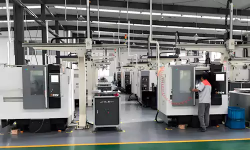
Technical capability forms the foundation of a successful partnership. Assess the supplier's equipment list, particularly their grooving-specific tooling and capabilities. Modern CNC lathes with live tooling provide greater flexibility for complex grooving requirements.
Quality assurance systems demonstrate commitment to consistent results. Look for certifications like ISO 9001. The supplier's measurement equipment should match your precision requirements.
Communication and responsiveness often differentiate adequate suppliers from exceptional ones. Your partner should provide clear technical feedback and proactive communication about potential challenges.
Ask these critical questions:
- What is your experience with similar materials and geometries?
- How do you handle engineering change requests?
- What quality documentation do you provide with shipments?
Conclusion
Precision grooving demands proper method selection, material understanding, and experienced partners. Master these elements for successful custom components.

-
Explore this link to understand how Lathe Grooving can enhance precision in rotational parts. ↩
-
Explore this link to understand the fundamentals of CNC lathe cutting and its applications in various industries. ↩
-
This resource will offer valuable strategies for enhancing chip control, which is essential for maintaining efficiency and product quality. ↩
-
Explore this link to understand the applications and benefits of titanium bone drill components in medical devices. ↩
