Confused about how metal parts get their precise shapes? Trying to understand the core process can be overwhelming. Metal machining removes material methodically to achieve exact designs, crucial for functional components.
Metal machining is a subtractive manufacturing process where material is precisely removed from a metal workpiece using cutting tools to create a part with the desired shape, size, and surface finish according to engineering drawings or CAD models.
This process is fundamental to modern manufacturing, creating everything from tiny screws to large engine components. Understanding the basics helps anyone involved in product design or manufacturing. Let's explore the key aspects of this essential technique.
What is metal machining?
New to manufacturing terms and wondering what "machining" really means? It sounds complex, but the basic idea is simple. Understanding machining helps you appreciate how metal products are actually made.
Metal machining refers to a family of processes where material is cut away from a raw piece of metal (like a block, bar, or casting) using specialized tools to achieve a precise final shape and size specified by a design.
Think of it like sculpting, but with metal and powerful machines instead of clay and hands. We start with more material than we need and carefully remove the excess. I've spent my whole career around these processes, starting on the shop floor and now running Allied Metal. It's all about controlled material removal.
The Core Concept: Subtractive Manufacturing
Machining falls under the umbrella of subtractive manufacturing. This is the opposite of additive manufacturing (like 3D printing), where material is added layer by layer. In machining:
- Starting Material: You begin with a workpiece, which could be a solid block, a round bar, a pre-formed casting, or forging. This workpiece is larger than the final part in at least some dimensions.
- Cutting Tools: Specialized tools, often made of hardened steel, carbide, or diamond, are used. The shape and material of the tool depend on the operation (drilling, milling, turning) and the metal being cut.
- Material Removal: The cutting tool engages with the workpiece, and through relative motion (either the tool moves, the workpiece moves, or both), it shears off small chips of metal.
- Controlled Process: This removal is not random. Sophisticated machines, often Computer Numerical Controlled (CNC), precisely guide the tool and/or workpiece according to programmed instructions derived from a digital design (CAD model1).
- Desired Outcome: The goal is to remove material until only the desired part geometry remains, meeting specific tolerances for dimensions, angles, and surface smoothness.
Essentially, metal machining shapes metal by cutting away unwanted portions. It's a versatile and highly accurate method for producing components across countless industries, from automotive and aerospace to medical and consumer electronics.
What is the process of metal work machining?
Curious about the journey from raw metal to a finished part? Seeing the steps involved clarifies how designs become reality. Let's break down the typical workflow in a machining operation.
The metal machining process generally involves interpreting the design, selecting material and tools, setting up the machine, performing cutting operations (like milling, turning, drilling), and inspecting the final part for quality assurance.
Turning a concept into a physical metal part involves several critical stages. At Allied Metal, we follow a rigorous process for every job, big or small, to ensure accuracy and quality. Skipping steps or rushing setup leads to problems down the line.
From Blueprint to Finished Part
Here’s a typical sequence of events in a CNC metal machining workflow:
- Design Interpretation:
- Input: We receive a technical drawing2 (blueprint) or a 3D CAD (Computer-Aided Design) model from the client, like Jacky the designer.
- Analysis: Our engineers or programmers review the design, noting dimensions, tolerances, surface finish requirements, and material specifications. We look for potential machining challenges early on.
- Material Selection and Preparation:
- Choice: The correct metal alloy (e.g., Aluminum 6061, Stainless Steel 304, Titanium Grade 5) is selected based on the design requirements.
- Sourcing: Raw stock (bar, plate, block) of the appropriate size is obtained.
- Prep: The material might be cut to a rough size suitable for loading into the machine.
- Process Planning & Programming:
- Strategy: We decide the sequence of operations (e.g., face mill first, then drill holes, then cut pockets).
- Tool Selection: The right cutting tools (end mills, drills, lathe tools) are chosen based on the material, operations, and required finish.
- CNC Programming: Using CAM (Computer-Aided Manufacturing) software, we generate the toolpaths and G-code instructions that will control the CNC machine's movements, speeds, and feeds.
- Machine Setup:
- Workholding: The metal workpiece is securely clamped onto the machine table (milling) or into the chuck (turning) using vises, fixtures, or chuck jaws. This is critical for accuracy and safety.
- Tool Loading: The selected cutting tools are loaded into the machine's tool holder or turret.
- Referencing: The machine needs to know the exact position of the workpiece and tools. This involves setting work offsets and tool length offsets.
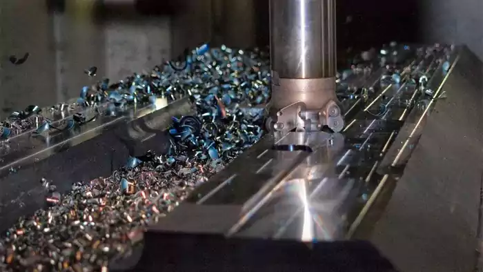
- Machining Operations:
- Execution: The CNC program is loaded, and the machine executes the cutting operations automatically, removing material step-by-step. Coolant is often used to manage heat and clear chips.
- Monitoring: A skilled machinist oversees the process, listening for unusual sounds, checking chip formation, and ensuring everything runs smoothly. Adjustments might be needed.
- Inspection and Quality Control:
- Measurement: After machining, the part is carefully measured using precision instruments3 (calipers, micrometers, CMM) to verify that all dimensions and tolerances meet the specifications.
- Surface Finish Check: The surface roughness is checked against the requirements.
- Deburring: Sharp edges or small burrs left by machining are often removed.
- Finishing (If Required):
- The part might undergo secondary processes like anodizing, plating, painting, or heat treatment.
- Final Approval & Shipping:
- Once the part passes all checks, it's ready for the customer.
This systematic approach ensures consistency and quality in machined metal parts.
What is a machinable metal?
Ever wondered why some metals cut easily while others fight back? Not all metals behave the same way under the cutting tool. Understanding machinability helps select materials and optimize the cutting process.
A machinable metal is one that can be cut efficiently and economically with good tool life and surface finish using standard machining processes. Factors like hardness, ductility, thermal conductivity, and chemical composition influence machinability.
From my experience, machinability is a crucial factor in quoting jobs and planning production. A "difficult-to-machine" metal means slower cutting speeds, faster tool wear, and potentially higher costs for the customer. We always factor this in.
Factors Influencing Machinability
There isn't a single number that defines machinability, but rather a combination of factors:
- Hardness: Harder metals generally resist cutting more, leading to increased tool wear4 and requiring slower cutting speeds. Extremely hard materials can be very difficult or impossible to machine with conventional tools.
- Ductility: Highly ductile metals (like some stainless steels or aluminum alloys) tend to form long, stringy chips that don't break easily. This can lead to poor surface finish and chip control issues (chips wrapping around the tool). They can also form a "built-up edge" on the tool, affecting accuracy.
- Tensile Strength: Higher strength materials require more force to cut, putting more stress on the tool and machine.
- Thermal Conductivity: Metals that conduct heat well (like aluminum) help dissipate heat generated during cutting away from the tool, which can improve tool life. Poor conductors (like titanium or stainless steel) concentrate heat at the cutting edge, leading to faster tool wear.
- Abrasiveness: Some alloys contain hard inclusions or particles (like silicon in some aluminum alloys or carbides in tool steels) that are abrasive and accelerate tool wear.
- Chemical Composition: Alloying elements significantly impact machinability. For example:
- Lead (Pb), Sulfur (S), Selenium (Se), Bismuth (Bi): Often added in small amounts to "free-machining" alloys (like 12L14 steel or 2011 aluminum). They help chips break easily and can reduce friction.
- Carbon (C): Increases hardness and strength in steel, generally reducing machinability above certain levels.
- Nickel (Ni), Chromium (Cr): Often found in stainless steels and superalloys, they increase strength, toughness, and work-hardening potential, making machining more challenging.
Examples of Machinability Ratings
Metals are often compared using a machinability rating, typically benchmarked against AISI 1212 steel (a free-machining steel) which is assigned a rating of 100%.
| Metal Example | Typical Machinability Rating (%) | Notes |
|---|---|---|
| AISI 1212 Steel | 100% | Benchmark free-machining steel |
| AISI 12L14 Steel | ~140-160% | Leaded, very easy to machine |
| Aluminum 6061-T6 | ~90% | Good machinability, common aluminum alloy |
| Aluminum 2011-T3 | ~150% | Free-machining aluminum (contains Pb, Bi) |
| Brass (C36000) | ~100-120% | Excellent machinability (contains lead) |
| Low Carbon Steel (1018) | ~70% | Fair machinability, gummy chips |
| Alloy Steel (4140) | ~60-65% | Moderate machinability, stronger |
| Stainless Steel 304 | ~40-45% | Difficult (ductile, work-hardens) |
| Stainless Steel 303 | ~70-75% | Free-machining stainless (contains S) |
| Titanium (Ti-6Al-4V) | ~20-30% | Very difficult (poor thermal conductivity) |
Note: Ratings are approximate and can vary.
Selecting a metal with good machinability can significantly reduce production time and cost, provided it still meets the functional requirements of the part.
What are the 4 machining processes?
Heard terms like milling and turning but not sure how they differ? Machining involves several core techniques to shape metal. Knowing the main processes helps understand how different features are created.
The four fundamental machining processes are generally considered Turning, Milling, Drilling, and Grinding. These cover the primary ways material is removed using cutting tools or abrasive wheels to create various shapes and features.
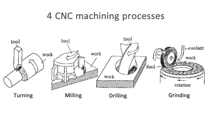
While there are many specialized machining methods, these four form the bedrock of most metal-cutting operations we perform daily at Allied Metal. Each uses a different relationship between the tool and the workpiece to achieve specific results.
The Core Four Explained
Let's look at each of these essential subtractive processes:
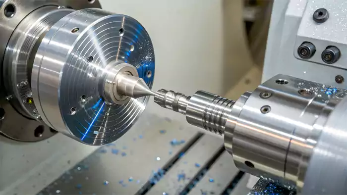
- Turning:
- Concept: The workpiece (usually cylindrical raw stock) rotates rapidly while a stationary single-point cutting tool moves linearly along its surface or across its face.
- Machine: Lathe (manual or CNC).
- Action: Primarily used to create cylindrical parts, tapers, threads, and faces on round components. Think of table legs, shafts, bolts, or flanges.
- How it Works: As the workpiece spins, the tool peels away material, reducing the diameter or cutting features into the face or along the length.
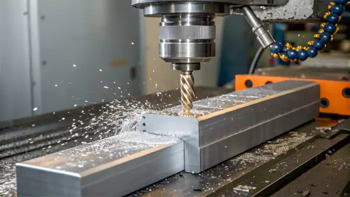
- Milling:
- Concept: A rotating multi-tooth cutting tool moves relative to a stationary workpiece to remove material.
- Machine: Milling machine (manual or CNC).
- Action: Used to create flat surfaces, slots, pockets, profiles, and complex 3D contours. Think of engine blocks, mold cavities, or complex brackets.
- How it Works: The rotating cutter's teeth shear off chips as the tool traverses across the workpiece surface or plunges into it. The workpiece is typically held in a vise or fixture on the machine table, which can also move.
- Drilling:
- Concept: Creating or enlarging round holes in a workpiece using a rotating cutting tool (drill bit).
- Machine: Drill press, milling machine, or lathe.
- Action: Simply makes holes. Often a precursor to other operations like tapping (threading) or boring (enlarging and finishing a hole accurately).
- How it Works: A rotating drill bit with two cutting edges at its point is fed axially into the material, removing chips through spiral flutes.
- Grinding:
- Concept: Using a rotating abrasive wheel (instead of a sharp cutting tool) to remove small amounts of material, achieving very high precision and smooth surface finishes.
- Machine: Grinding machine (surface grinder, cylindrical grinder, centerless grinder).
- Action: Primarily used for finishing operations to achieve tight tolerances and excellent surface quality, or for machining very hard materials that are difficult to cut with conventional tools.
- How it Works: The abrasive particles on the grinding wheel act like thousands of microscopic cutting edges, shearing off tiny chips of material.
Other Important Processes
While these four are often cited as the main ones, other machining processes are also crucial in manufacturing:
- Boring: Enlarging an existing hole to a precise diameter and good finish, often done on a lathe or milling machine.
- Sawing: Cutting material to length or shape using a blade with teeth.
- Broaching: Using a tool with successively larger teeth to create specific shapes (like keyways or splines) in a single pass.
- Electrical Discharge Machining (EDM): Using electrical sparks to erode material, often used for hard metals or complex shapes difficult to achieve otherwise.
Understanding these fundamental processes provides a solid foundation for comprehending how metal parts are manufactured to precise specifications.Conclusion
Metal machining is a vital subtractive process using tools to cut metal into precise shapes. Key methods include milling, turning, drilling, and grinding, each suited for different features and finishes.
Footnotes:
-
Learning about CAD models will deepen your knowledge of how digital designs influence machining processes and outcomes. ↩
-
Understanding technical drawings is essential for accurate manufacturing; this link offers valuable guidance on interpreting them effectively. ↩
-
Exploring precision instruments will enhance your knowledge of quality control in machining and improve your inspection techniques. ↩
-
Learning about tool wear can lead to better maintenance practices and longer tool life, enhancing overall machining performance. ↩
